EasyManuals Logo

BST CCD CAM 100 User Manual

BST CCD CAM 100
198 pages
To Next Page IconTo Next Page
To Previous Page IconTo Previous Page
Page #65 background imageLoading...
Page #65 background image
Electrical Connection
7
CCD CAM 100 – Installation and Operating Manual 65/198
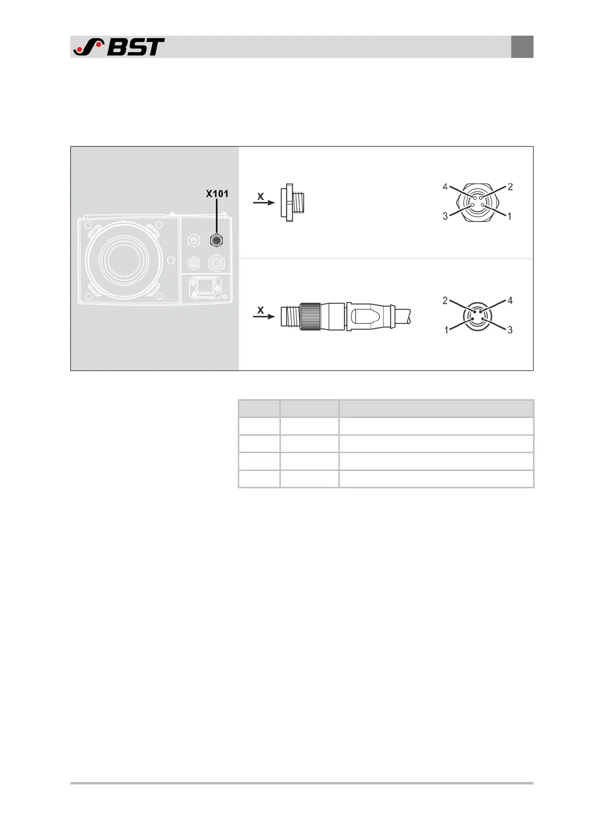
7.3.6 X101 - CAN Bus (Socket)
Further CAN bus participants (e.g. a second CCD camera
CCDCAM100) are connected to the CAN bus interface of the CCD
camera unit using a 4-pin micro style connector M8.
View X
Socket (female)
View X
Connector (male)
Fig.39: Contact assignment of the plug connector
Contact Function Remark
1 +24V Power supply +24V
2 CAN-H CAN high
3 CAN-GND Ground power supply
4 CAN-L CAN low

Table of Contents

Questions and Answers:

Question and Answer IconNeed help?

Do you have a question about the BST CCD CAM 100 and is the answer not in the manual?

BST CCD CAM 100 Specifications

General IconGeneral
BrandBST
ModelCCD CAM 100
CategoryAccessories
LanguageEnglish

Related product manuals