7
Electrical Connection
66/198 CCD CAM 100 – Installation and Operating Manual
7.4 Establishing the Cable Connections
7.4.1 Standard Application
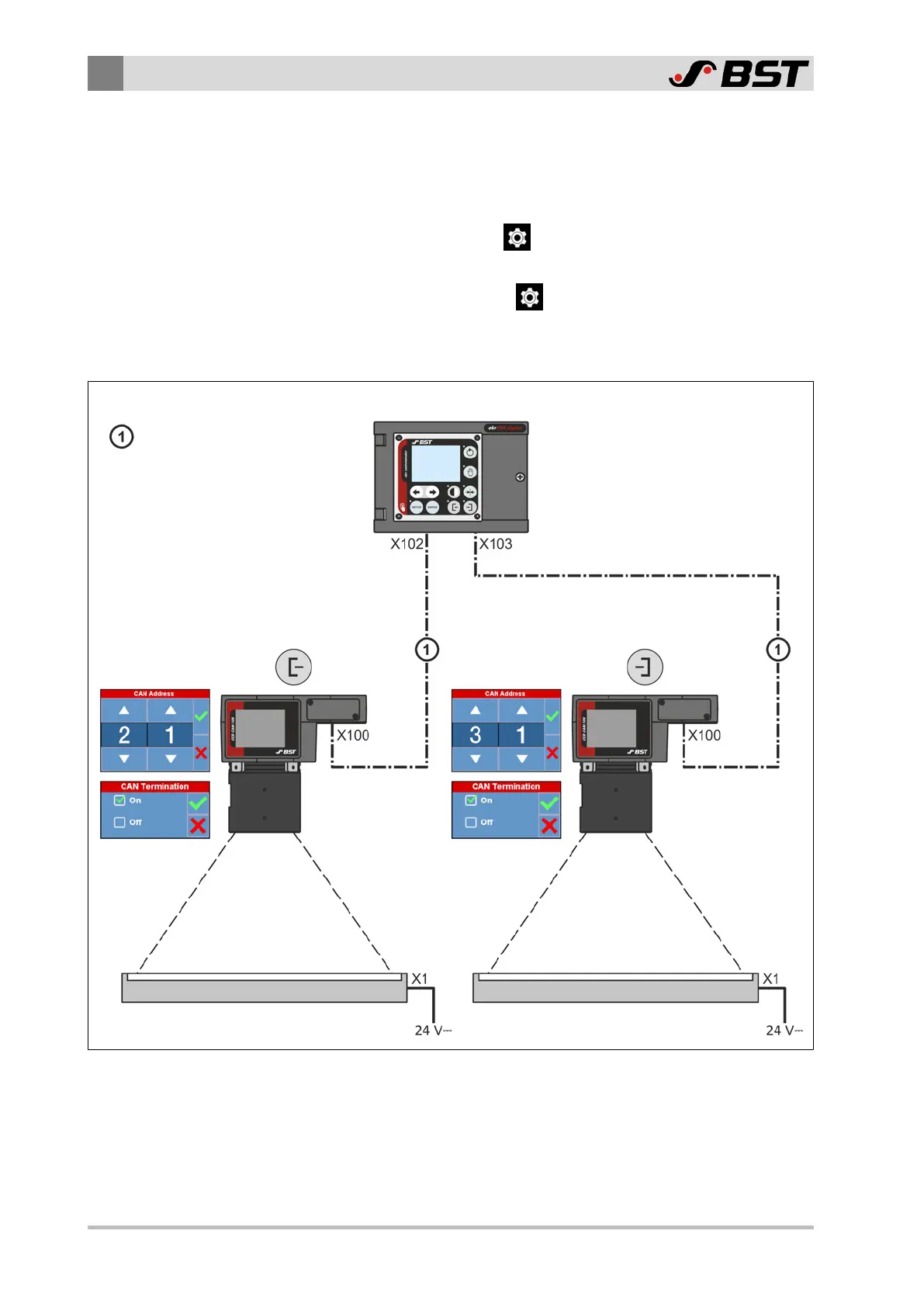
›› The CAN bus addresses of the CCD cameras are set as represented
in the figure (Menu
\ Network \ CAN Open \ CAN Address).
›› The internal CAN bus terminating resistors of the CCD camera
are activated (Menu
\ Network \ CAN Open \ CAN Termin-
ation).
►
Establish the cable connections according to the figure.
CAN bus extension
2 m (131 993)
5 m (131 994)
10 m (131 995)
or
spiral cable 0.5/2 m (168 176)
Light box 1 Light box 2
ekr 500 digital Unit Touch
Fig.40: Cable connections standard application
7.4.2 Special Applications
►
Establish the cable connections according to the connecting
diagram provided.
 Loading...
