Electrical Connection
7
CCD CAM 100 – Installation and Operating Manual 63/198
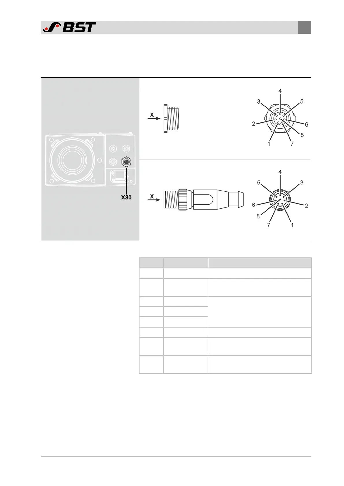
7.3.4 X80 - Digital Inputs / Outputs
The input / output signals are connected to the CCD camera using
a 8-pin M12 micro-style connector.
View X
Socket (female)
View X
Connector (male)
Fig.37: Contact assignment of the plug connector
Contact Function Remark
1 GND Ground for contacts 2…5
2 Input / output 1
Power supply 24V⎓ for external
encoder
3 Input / output 2
Digital input / output 24V⎓4 Input / output 3
5 Input / output 4
6 EXT_GND Insulated ground for contacts 7 and 8
7 EXT_GEAR
Input for external GEAR pulse
(Synchronization)
8 EXT_RESET
Input for external RESET pulse
(Synchronization)
The technical specifications of the inputs and outputs can be
found in chapter Technical Specifications, page 34.