Chery QQ Service Manual Transmission System
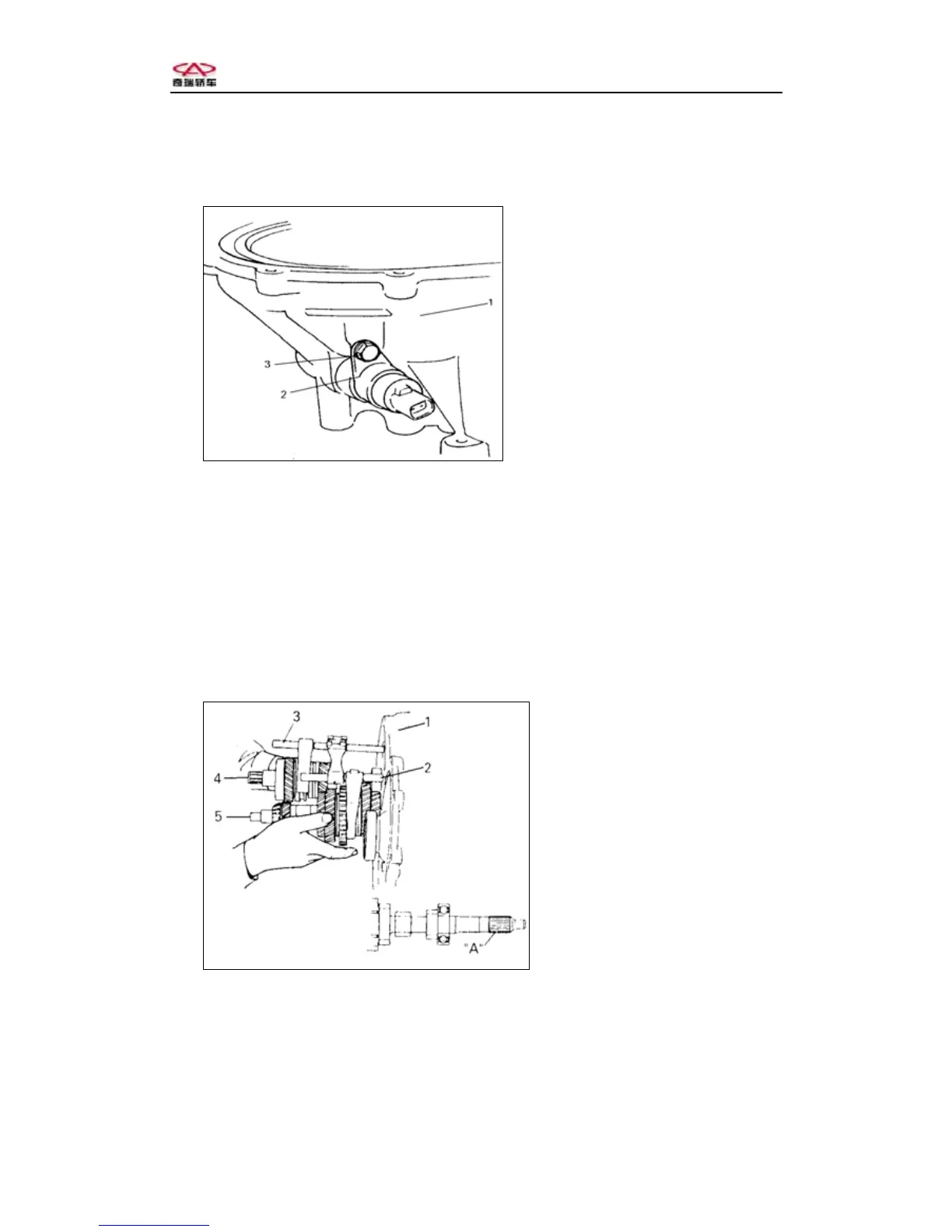
2, Spread lubricant on the “O” ring and gear, install the speedometer driven
gear assembly,and then screw down the torque.
Torque:8~12 N·m
1-Clutch case
2-Speedometer driven gea
assembly
3-Bolt
Fig.3-65
Notice: When installing speedometer driven gear, turn the differential ring driven gear
lightly to joggle the gear. Do not knock the cracks on the speedometer case, otherwise
the case may be broken.
3, Hold the input shaft assembly, output shaft assembly, 1st, 2nd shift
fork assembly and 3rd, 4th Shift fork assembly and fix them on the clutch case.
Notice: Use hammer to rivet the input shaft right bearing into clutch case。
Be sure output shaft and differential ring driven gear are joggled。
Notice:In order to protect oil seal,twine the insulating tape to input shaft
splined hub。
1-Clutch case
2-1st, 2nd Shift for
shaft assembly
4-Input shaft assembly
5-Output shaft assembly
Fig.3-66
4, Install the reverse shift fork, screw down the bolt。
Torque :18~28 N·m
Notice: When installing the reverse shift fork, keep the distance 5mm from the end of
shift fork and the shaft hole.
-84-
Chery Automobile Co., Ltd