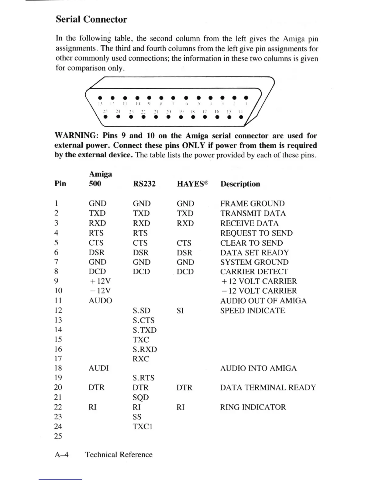
Serial Connector
In the following table, the second column from the left gives the Amiga pin
assignments.
The
third and fourth columns from the left give pin assignments for
other commonly used connections; the information in these two columns
is
given
for comparison only.
• • • • • • • • • • • • •
I'
12
II
In
'l
7 h
~
-+
'\
2 I
25
~-+
~;
.':1
211
1\)
IS 17
Ifl
15
1-+
• • • • • • • • • • • •
WARNING: Pins 9
and
10 on the Amiga serial connector
are
used for
external power. Connect these pins ONLY if power from them
is
required
by
the
external device. The table lists the power provided
by
each
of
these pins.
Pin
I
2
3
4
5
6
7
8
9
10
11
12
13
14
15
16
17
18
19
20
21
22
23
24
25
Amiga
500
GND
TXD
RXD
RTS
CTS
DSR
GND
DCD
+12V
-12V
AUDO
AUDl
DTR
RI
RS232
GND
TXD
RXD
RTS
CTS
DSR
GND
DCD
S.SD
S.CTS
S.
TXD
TXC
S.RXD
RXC
S.RTS
DTR
SQD
RI
SS
TXCI
A-4
Technical Reference
HAYES®
GND
TXD
RXD
CTS
DSR
GND
DCD
SI
DTR
Rl
Description
FRAME GROUND
TRANSMIT DATA
RECEIVE DATA
REQUEST TO SEND
CLEAR
TO
SEND
DATA SET READY
SYSTEM GROUND
CARRIER DETECT
+
12
VOLT CARRIER
-
12
VOLT CARRIER
AUDIO OUT
OF
AMIGA
SPEED INDICATE
AUDIO INTO AMIGA
DATA TERMINAL READY
RING INDICATOR