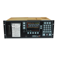
System 3505 Installation & Operation Manual
Digitize, Inc. 700248-0002 Rev. C 02/16
Specification Subject to Change Without Notice
14-2
Alarm Monitor Card, P/N: 400381. The Alarm Monitor card can be plugged into any
available card slot in the SYSTEM 3505.
• Input Panel Assembly, P/N: 450203. The Input Panel Assembly, 3 1/2" X 19" rack
mountable assembly with sheet metal, allows for up to 20 circuits of telegraph to be
connected into the SYSTEM 3505. There are two screw terminals for each input
circuit. The Input Panel Assembly also holds the input cards themselves (see different
inputs available). The Input Panel Assembly is connected to the Alarm Monitor via a
26-pin keyed ribbon cable.
• Ribbon Cable, P/N: 450145. The Ribbon Cable is a 26 conductor with a connector at
each end of the cable. The normal length is six feet. Up to 20 feet is available but must
be specified.
• 100 MA Input PCB, P/N: 400332. The 100 MA Input PCB is a plug in board which
is inserted into the input panel assembly in any one of the 20 locations to allow for
alarm reception from a 100 MA closed loop circuit.
• 24 VDC Input PCB, P/N: 400334. The 24 VDC Input is a plug-in board which is
inserted into the input panel assembly in any one of 20 locations to allow for
reception from a 24 VDC alarm source.
• Normally Closed Input PCB, P/N: 400333, The NC Dry Contact Input is a plug-in
board which is inserted into the input panel assembly in any one of the 20 locations to
allow for alarm reception from any normally closed dry relay contact.
• Normally Open Input PCB, P/N: 400335. The NO Dry Contact Input is a plug-in
board which is inserted into the panel assembly in any one of the 20 locations to allow
for alarm reception from any normally open dry relay contact.
14.3 OPERATION
The TCI option, when connected to the telegraph circuit, will input the code to the SYSTEM
3505 for processing. The code will be processed and printed out on a round-by-round basis.
The screen on the SYSTEM 3505 will display the incoming circuit number, as well as show the
box decoding. It will also display that the alarm is an incoming telegraphic alarm. The audible
alert will be activated; press the CLEAR button to silence the deep tone.
After the first round of the telegraphic code, the SYSTEM 3505 will display the message that
was programmed for that particular telegraphic code number. At the end of the last round the
printer will log the top line of the programmed message along with the date and time. The
ACK button will be lit and the beeper will activate a tone. Press the ACK button to
ACKnowledge the telegraphic alarm and silence the beep tone. The printer will log the
ACKnowledge, along with the date and time.
When the box can be cleared from the system, the LED on the CLEAR button will blink. To
clear a telegraphic coded alarm, press the CLEAR button when the LED is blinking. This will
clear the display, and the printer will log that the alarm was cleared along with the date and
time.
14.3.1
Connections
After the desired input type has been selected, connect the input according to the
figure associated with input type below:
100 MA Loop
24 VDC