System 3505 Installation & Operation Manual
Digitize, Inc. 700248-0002 Rev. C 02/16
Specification Subject to Change Without Notice
8-1
8 Q-MUX MULTIPLEX SYSTEM
8.1 OVERVIEW
The Q-Mux is a low cost multiplex system. Two wires are used to power the ID modules (i.e.
Q-1C, Q-1CL, Q-1R, Q-I/O, Q-EOL), to send commands to the modules and to receive their
data. Commands from the Q-Node to the ID modules take the form of modulating the Buss
voltages between 0 and 10v. The data returned from the modules is in the form of increased
Buss current.
Each Q-node can control up to 63 mix/matched ID modules. Up to 32 Q-Nodes may be used
in one system. Total range of the Q-Mux system is 5,000 feet from the System 3505 to the
last Q-Node and 5,000 feet from the Q-Node to the last ID module. ID modules may be set to
any address from 1 to 63. Addresses are stored on an internal EEPROM and can be changed
by the Q-Mux Programmer.
NOTE: The Q-Mux multiplex system is not compatible with the Digitize Multiplex system
referenced in Section 15 of the SYSTEM 3505 Installation and Operation Manual.
To add a Q-MUX point ID module the Q-Mux Option (P/N 010001-0094) must be purchase,
along with a minimum of one Q-Mux node for the SYSTEM 3505.
Q-Mux Node…………………………………………………………. 425190-0001
Q-1C, Digital Addressable Contact………………………………….. 425182-0001
Q-1CL, Latching Addressable Contact………………………………. 425182-0003
Q-1R, Relay Addressable Contact…………………………………… 425182-0004
Q-I/O, Input/Output Addressable Contact…………………………… 425182-0005
Q-EOL, End-of-Line Addressable Contact…………………….…….. 425182-0006
Q-Mux Programmer………………………………………………….. 425184-0001
Refer to the Installation Drawing 800321 for installation details.
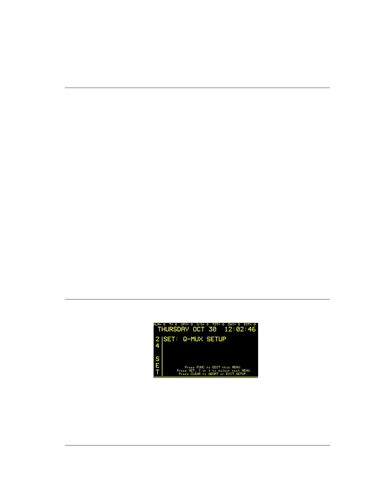
8.2 Q-MUX OPTION SET UP
Enter “24”, press the SET button and the display will read:
Press FUNC to edit this menu. Enter password if prompted. The display will read: