System 3505 Installation & Operation Manual
Digitize, Inc. 700248-0002 Rev. C 02/16
Specification Subject to Change Without Notice
14-3
NO Dry Relay Contacts
NC Dry Contacts
The unit will take care of “OPEN” or “CLOSED” index code wheels automatically.
The different type of input PCB’s plug into the input panel assembly with the five
gold pins to the left side (connector side view).
CAUTION! Be sure of input card type before connecting to any line. Failure
to verify card type may result in damage to the equipment and void any
warranty.
The ribbon cable which connects the input panel assembly to the alarm monitor
card is keyed. Connect one side to the alarm monitor card via the rear header
labeled TCI. Connect the other end to the connector in the middle of the input
panel assembly. The Alarm Monitor Card will plug into any blank slot in the
SYSTEM 3505.
14.4 TELEGRAPH CHECK OPTION SETUP
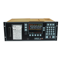
Enter “27”, press the SET button and the display will read:
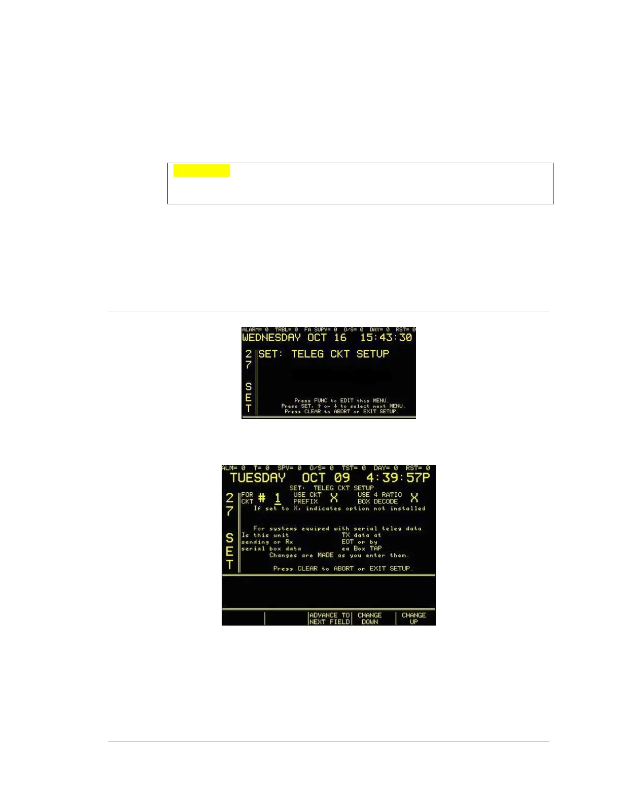
Enter password, if prompted. Press the FUNC button to select this screen. The next screen will
read:
Press the FUNC key, or the ADVANCE TO NEXT FIELD programmable key, to move
between fields. Use ↑ or ↓ , or the CHANGE UP/CHANGE DOWN programmable keys, to
change values. Enter Ckt (circuit) 1-40. Press the CLEAR key to save changes and return to
main set menu.