System 3505 Installation & Operation Manual
Digitize, Inc. 700248-0002 Rev. C 02/16
Specification Subject to Change Without Notice
14-4
14.4.1
Selt Test Option Setup
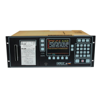
Enter “28”, press the SET button and the display will read:
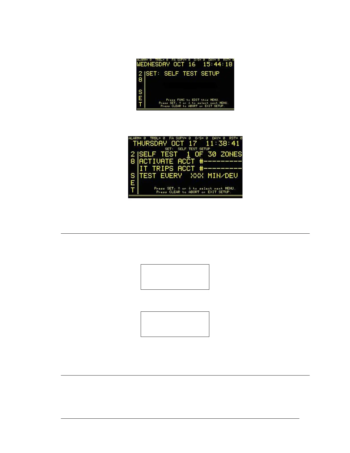
Press the FUNC button to select this screen. If prompted, enter password. The
following screen will read:
Press the FUNC key to move between fields. Use ↑ or ↓ to change values. Press
the CLEAR key to save changes and return to main set menu.
14.5 CABLE SUPERVISION
When one or more Alarm Monitor Cards are installed and the ribbon cable (P/N 450145) is
removed between the Alarm Monitor Card and the TCI rear panel, the following alarm message
will display:
RIBBON CABLE (S)
TO ALARM MONITOR
CARD IS REMOVED
JAN 01 12:23:45
When all cables are reconnected, the display will show:
RIBBON CABLE (S)
TO ALARM MONITOR
CARD IS REPLACED
JAN 01 12:23:45
In either case, press ACK to silence alarm.
14.6 CIRCUIT NUMBER SELECT
A four position dip switch is provided on the Alarm Monitor Card to select the board number
which, in turn, selects the starting circuit number. If more than one Alarm Monitor Card is
plugged in, then no two cards can have the same switch setting. To start at Ckt #1, set all four
switches on SWP1 to open. For other settings, refer to Figure 14-1.