System 3505 Installation & Operation Manual
Digitize, Inc. 700248-0002 Rev. C 02/16
Specification Subject to Change Without Notice
7-19
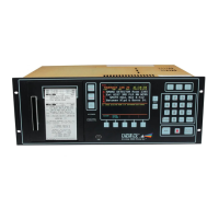
The original sequence to answer the phone was 1, 2, 3, 4, 5, 6, 7. When selection
#3 was picked, the printer printed the new sequence, 3, 1, 2, 4, 5, 6 and 7.
7.4.15
DDI-9E LED Indicators
Power (Green LED)
A steady illumination (ON) indicates 6-12 VDC power applied.
Line 1/Line 2 (Red LED)
No illumination (OFF) indicates the connected phone line is OK (also checks for
dial tone).
A steady illumination (ON) indicates DDI-9/10E is answering the phone.
A flashing LED indicates phone line problems. Failure of both phone lines will
cause LED indicators to flash in unison.
Line 1 and Line two LED’s flashing alternately indicates SYSTEM 3505
commanded DDI-9/10E not to answer the phone. This feature is used when
redundant SYSTEM 3505s are in service (i.e. one DDI-9/10E is on line, while
the backup DDI-9/10E is off Line).
Computer (Amber LED)
A flashing LED indicates data being sent to SYSTEM 3505. The LED should
flash at least once every 30 seconds or more.
Printer (Amber LED)
A flashing LED indicates data is being sent to parallel line printer.
7.5 Redundant Operation
Redundant operation can take several forms. When using a redundant head end, one dual-line
DDI-9/10E can be installed on each of the redundant units. The online unit will answer the
phone. The backup unit will be in standby. Both DDI-9/10E units will have the phone lines in
parallel. Or, one dual-line DDI-9/10E may be used between the redundant SYSTEM 3505
units. Simply route the RS-232 signals via the T-Bar so that the online unit has access to the
DDI-9/10E.
Fire code requires two phone lines to the monitoring equipment. On SYSTEM 3505 units with
DDI-9/10E, if the first phone line is unable to make a connection, the phone automatically
hunts to the second phone line. (Please note: The hunt feature is provided by the local phone
company, not Digitize, Inc. equipment.).