10.2 Basic information
10.2.1
Slots and features
PCH
Indicate
CSS
TPM
Slot 2 (CPU 1) Riser slot 1
Battery
SATA
0-3
Slot 1 (CPU 1)
Slot 8 (CPU 2) Riser slot 2
Rear Serial
PWR
ODD
SATA
ODD
USB 3.0
PSU 1
PSU 2
JP3
1
JP2 JP1
1
2
MICRO
SD
HDD LED3
Slot 7 (CPU 2)
Slot 6 (CPU 2)
Slot 5 (CPU 2)
OCP 3.0 Slot
CPU 2 DIMM-1M
CPU 2
SMB3
PWR 5
PWR 1
FAN6_SYS
Clear RTC
iRMC
S6
FRONT VGA
REAR VGA
PWR 4
PWR 3
PWR 2
FAN5_SYS
FAN4_SYS
FAN3_SYS
FAN2_SYS
FAN1_SYS
MCIO 8
PWR 6
MCIO 7
MCIO 6
MCIO 5
MCIO 4
MCIO 3
MCIO 2
MCIO 1
CPU 1
PWR 7
CPU 2 DIMM-2M
CPU 2 DIMM-1L
CPU 2 DIMM-2L
CPU 2 DIMM-1K
CPU 2 DIMM-2K
CPU 2 DIMM-1
CPU 2 DIMM-2
CPU 1 DIMM-1D
CPU 1 DIMM-2D
CPU 1 DIMM-1C
CPU 1 DIMM-2C
CPU 1 DIMM-1B
CPU 1 DIMM-2B
CPU 1 DIMM-1A
CPU 1 DIMM-2A
CPU 2 DIMM-2N
CPU 2 DIMM-1N
CPU 2 DIMM-2P
CPU 2 DIMM-1P
CPU 2 DIMM-2Q
CPU 2 DIMM-1Q
CPU 2 DIMM-2R
CPU 2 DIMM-1R
CPU 1 DIMM-2E
CPU 1 DIMM-1E
CPU 1 DIMM-2F
CPU 1 DIMM-1F
CPU 1 DIMM-2G
CPU 1 DIMM-1G
CPU 1 DIMM-2H
CPU 1 DIMM-1H
PWR 8
NC-SI
HDD LED1
SMB 1
PWR M2
* Shared LAN (top)
Management LAN
(bottom)
VROC
HDD LED2
INTERPOSER 1
Thermal
Sensor
J
J
SMB 2
2x USB 3.0
and VGA
2x LAN *
FRONT PANEL
SATA
4-7
19
Slot riser card
Riser card
GPGPU Riser
Slot 9
Slot riser card
Riser card
Slot 9
Slot 10
or
Slot riser card
Riser card
GPGPU Riser
Slot 3
Slot riser card
Riser card
Slot 3
Slot 4
or
PSU1
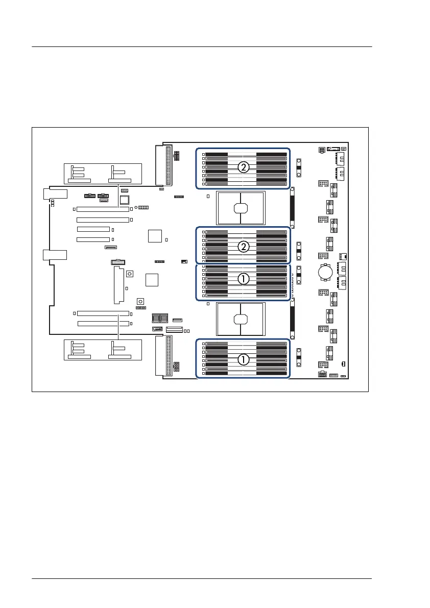
Figure 193: Slots of the main memory
1 CPU 1 memory slots 2 CPU 2 memory slots
Memory configuration for 1DPC configuration
–
Eight channel DDR5 memory architecture (per CPU), 1 DIMM slot per
channel
–
16 memory DIMM sockets (8 per CPU)
–
Supports non-3DS RDIMM, 3DS RDIMM and 9x4 RDIMM
–
UDIMM, SODIMM and LRDIMM are not supported
Main memory
332 Upgrade and Maintenance Manual RX2540 M7
 Loading...