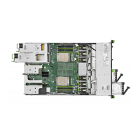
10 Power cable
▶
Connect the power cable to the connector “PWR 4” on the system board.
▶
Connect the signal cable to the connector “SMB2” on the system board.
The cables are equipped with labels showing the right connector.
For the cable plan, see "Appendix B" on page
559.
CAUTION
Incorrect cabling may cause wrong LED identification of the HDD/SSD.
Misleading LED could lead to swapping out the wrong HDD/SSD, and
that will result in data loss.
▶
Check the correct cabling using the labels on the cables and the
cable plans.
Concluding steps
▶
"Installing the fan cage" on page
77.
▶
"Reassembling" on page 59.
▶
"Connecting the power cord" on page 65.
▶
"Switching on the server" on page 71.
▶
If applicable, "Installing the front cover with lock" on page 71.
7.7.2 Removing the SAS expander board
Upgrade and Repair Unit
(URU)
Hardware: 10 minutes
Tools: Phillips PH2 / (+) No. 2 screw driver
Preliminary steps
▶
"Locating the defective server" on page
47.
▶
If applicable, "Removing the front cover with lock" on page 49.
Hard disk drive (HDD) / solid state disk (SSD)
RX2540 M7 Upgrade and Maintenance Manual 207
 Loading...