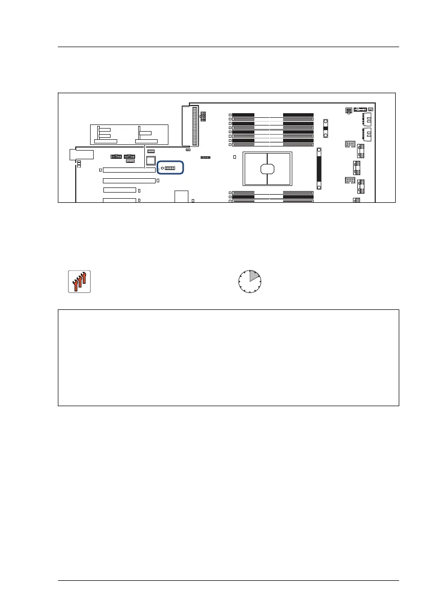
17.4.2 Position of the TPM
TPM
Slot 8 (CPU 2) Riser slot 2
PSU 1
JP3
1
MICRO
SD
HDD LED3
Slot 7 (CPU 2)
Slot 6 (CPU 2)
Slot 5 (CPU 2)
CPU 2 DIMM-1M
CPU 2
SMB3
PWR 5
FAN6_SYS
iRMC
S6
FRONT VGA
REAR VGA
PWR 4
FAN5_SYS
MCIO 8
PWR 6
MCIO 7
MCIO 6
MCIO 5
PWR 7
CPU 2 DIMM-2M
CPU 2 DIMM-1L
CPU 2 DIMM-2L
CPU 2 DIMM-1K
CPU 2 DIMM-2K
CPU 2 DIMM-1
CPU 2 DIMM-2
CPU 2 DIMM-2N
CPU 2 DIMM-1N
CPU 2 DIMM-2P
PWR M2
VROC
J
J
SMB 2
2x USB 3.0
and VGA
FRONT PANEL
Slot riser card
Riser card
GPGPU Riser
Slot 9
Slot riser card
Riser card
Slot 9
Slot 10
or
PSU1
Figure 334: Position of the TPM on the system board
17.4.3 Installing the TPM
Field Replaceable Unit
(FRU)
Hardware: 5 minutes
Software: 5 minutes
Tools: – Phillips PH2 / (+) No. 2 screw driver (for cover 2)
–
Bit screw driver
–
TPM bit insert
(*)
(*)
For Japan:
– TPM module fixing tool (S26361-F3552-L909)
Preliminary steps
▶
In case of Windows as operating system, "Suspending BitLocker
functionality" on page
89.
▶
If applicable, "Removing the front cover with lock" on page 49.
▶
"Shutting down the server" on page 50.
▶
"Disconnecting the power cord" on page 50.
▶
"Getting access to the component" on page 55.
System board and components
RX2540 M7 Upgrade and Maintenance Manual 493
 Loading...