106 E3 Series Installation/Operation Manual — P/N 9000-0574:I 11/04/10
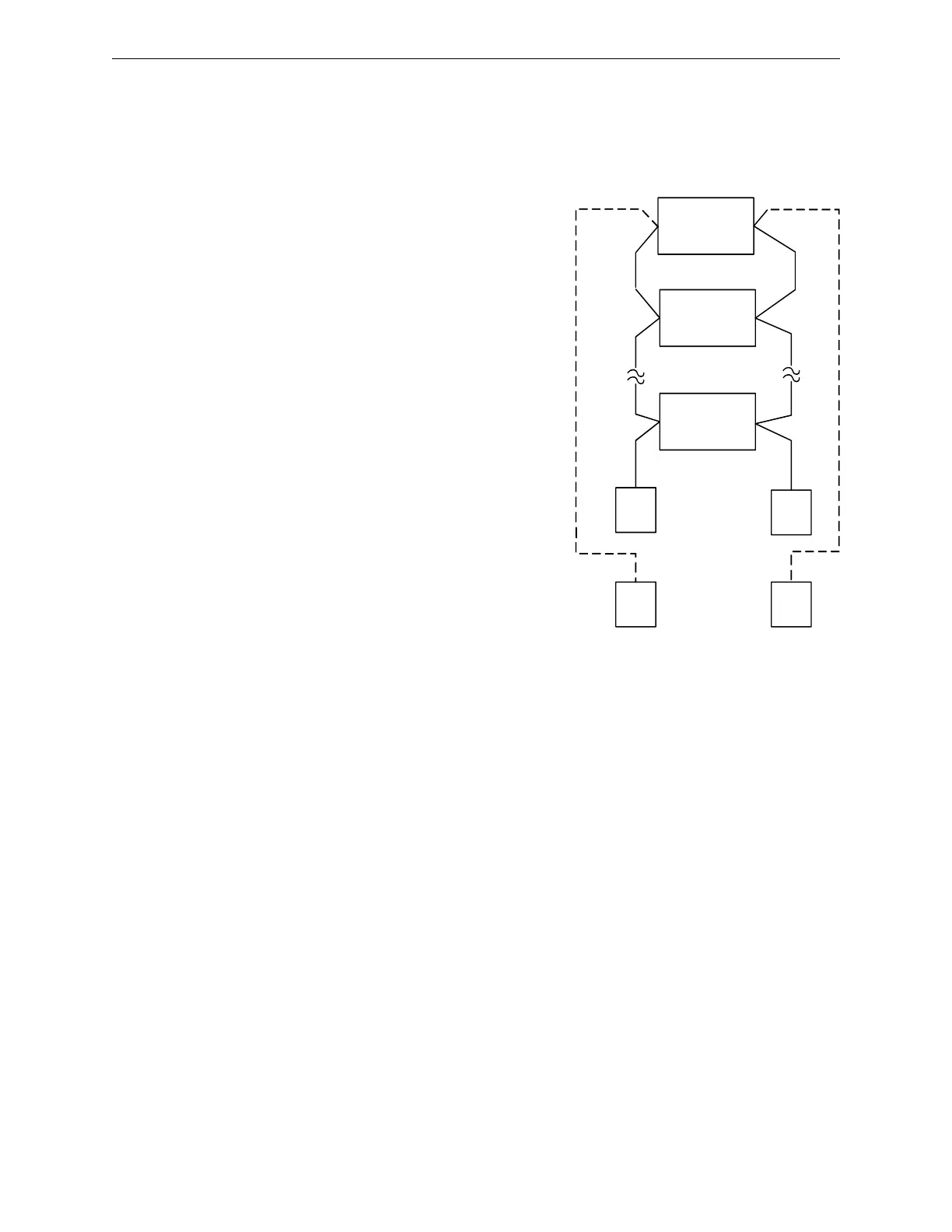
E3 Series System Connections Intelligent Loop Interface - Slave Board (ILI-S-E3) Connections
INPUT/CONTROL
MODULE
NCM-1
ILI-S-E3
B (-)
A (-) A (+)
B (+)
DOTTED LINES INDICATE CLASS A,
STYLE 6 WIRING.
SMOKE/HEAT
SENSOR
3.4 Intelligent Loop Interface - Slave Board (ILI-S-E3)
Connections
3.4.1 Signaling Line Circuits
Figure 3.4.1.1 Signaling Line Circuits
The ILI-S-E3 provides two (2), 24 VDC Class A, Style
6, 7 or Class B, Style 4 signaling line circuits. See
Figure 3.4.1.1 for wiring information. Style 7 wiring
requires the use of an M500X Isolator Module, on both
sides of a device.
Wiring Instructions
SLC 1 Style 4 TB4-8 (+), TB4-7 ( - )
SLC 2 Style 4 TB4-4 (+), TB4-3 ( - )
SLC 1 Style 6 TB4-8 out, TB4-6 return
TB4-7 out, TB4-5 return
SLC-2 Style 6 TB4-4 out, TB4-4-2 return
TB4-3 out, TB4-1 return
(Polarity markings indicate the polarity that should be
maintained throughout the circuit. Polarity connected
to the circuit must be observed on all devices).
Circuit Ratings
24 VDC (nominal)
Current: 0.048 amp max. (supervisory)
0.136 amp max. (alarm)
0.100 amp max. Steady State
(short circuit)
40 Ohms max. line impedance
0.5 µf max. line capacitance
Ground fault test impedance: Zero ohms
Wiring: 18 AWG minimum, twisted-pair, unshielded
Power-limited Supervised

 Loading...


