E3 Series Installation/Operation Manual — P/N 9000-0574:I 11/04/10 33
Cabinets Installation
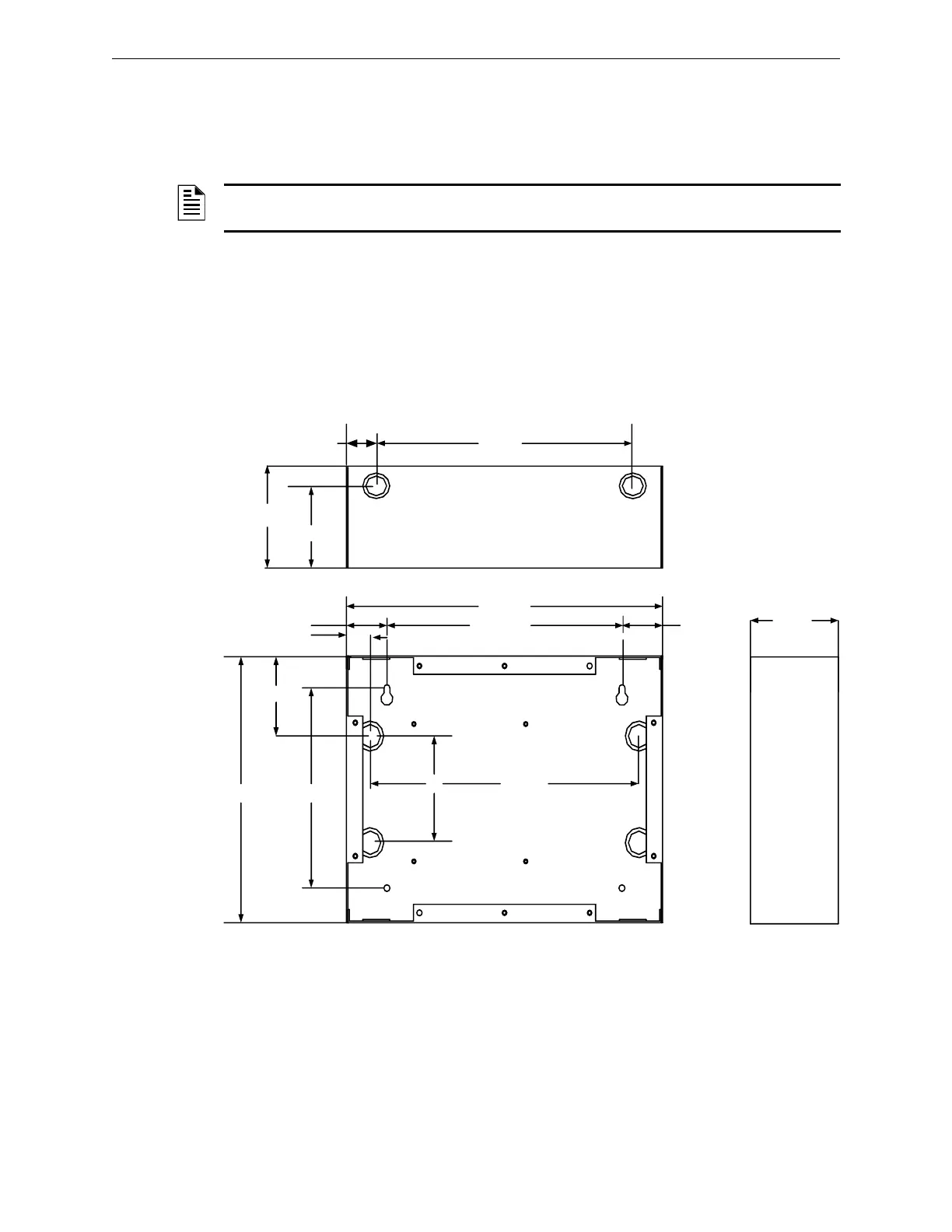
2.5.3.1 E3BB-FLUSH-LCD, CAB A2, Remote Flush Annunciator
Backbox Installation
1. To prepare the mounting site, pre-drill four (4), #10 screws using the dimensions shown in
Figure 2.5.3.1.1. Use four (4), #10 screws.
2. Secure with two (2), #10 screws in the two-hole mounting pattern as shown in Locations 1 and
2 of Figure 2.5.3.1.1.
3. Set the backbox over the top, two-hole mounting pattern, and hang the backbox over the two
screw heads.
4. Insert and secure two (2), #10 screws in the two-hole mounting pattern as shown in Locations
3 and 4 of Figure 2.5.3.1.1.
Figure 2.5.3.1.1 E3-BB-FLUSH-LCD, CAB A2, Remote Flush Annunciator Backbox
Installation
NOTE: If the fasteners are anchored to wallboard, use #10 wall anchors. Mountings to concrete
walls should be backed by plywood to insulate the equipment from possible condensation.
BACKBOX
13 1/4"
9 27/32"
1"
1 45/64"
3"
1 13/64"
10" 7 1/2"
4" 11 1/4"
BACKBOX TOP
10 ¾”
1 1/4”
3 5/8”
4 1/2”
4 1/2"
1 45/64"
1 2
43

 Loading...


