48 E3 Series Installation/Operation Manual — P/N 9000-0574:I 11/04/10
Installation Cabinets
2.5.6.4 Cabinet B, Backbox Sub-Assembly Installation (Typical)
1. Mount the ILI-MB-E3/ILI95-MB-E3 over the standoffs in the backbox and secure the eight,
(8), standoffs, (3/16” hex, #4-40 x 1.0”) in the eight-hole mounting pattern as shown in
Location 1 of Figure 2.5.6.4.2. (Note: PCB orientation).
2. Mount the DACT-E3 and the RPT-E3 on top of the ILI-MB-E3/ILI95-MB-E3 and secure the
eight (8), screws (#4-40 x 3/8”) into the eight (8), standoffs as shown in Location 2 of
Figure 2.5.6.4.2. (Note: PCB orientation).
3. Set the PM-9/PM-9G over the standoffs in the backbox and secure the six (6), screws (#4-40 x
3/8”) in the six-hole mounting pattern as shown in Location 3 of Figure 2.5.6.4.2. (Note: PCB
orientation).
4. Place the batteries in the backbox. The cabinet will accommodate two (2) batteries up to a
maximum of 18 amp/hours capacity.
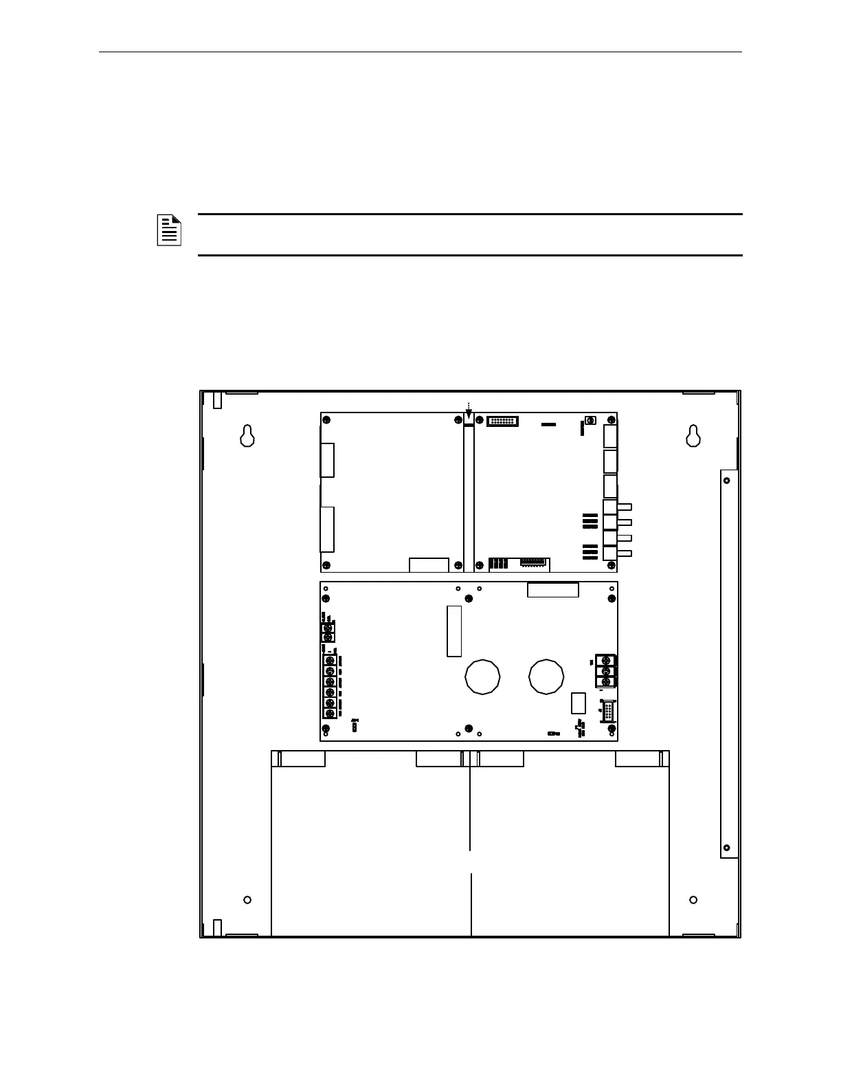
Figure 2.5.6.4.1 Cabinet B, Backbox Sub-Assembly (Standard View)
NOTE: You can replace the DACT-E3/RPT-E3 with the ANX and mount the ANX on top of the ILI-
MB-E3/ILI95-MB-E3.
BATTERIES
ILI-MB-E3/ILI95-MB-E3
DACT-E3
RPT-E3
PM-9/PM-9G
PM-9/PM-9G PCB

 Loading...


