112 E3 Series Installation/Operation Manual — P/N 9000-0574:I 11/04/10
E3 Series System Connections Intelligent Loop Interface XP95-Slave Board Connections
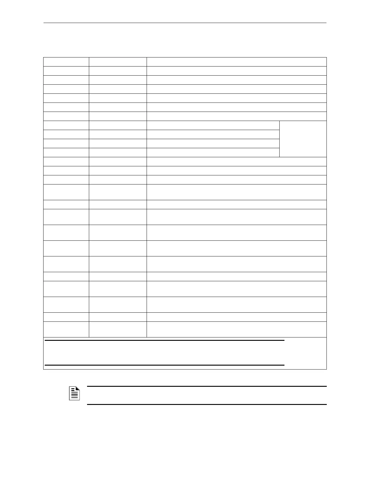
3.5.3 Intelligent Loop Interface XP95 - Slave Wiring Connections
Table 3.5.3.1 lists the field wiring connections for the ILI95-S-E3.
Designation Description Comments
TB1-1, TB1-3 +24 V IN +24 VDC Input
TB1-2, TB1-4 GND Common negative from PM-9/PM-9G TB4-2
TB4-1 SLC 2 A- SLC 2 Style 6 / 7 Return (See Note 1)
TB4-2 SLC 2 A+ SLC 2 Style 6 / 7 Return (See Note 1)
TB4-3 SLC 2 B- SLC 2 Style 4 / 6 / 7 Out (See Note 1)
TB4-4 SLC 2 B+ SLC 2 Style 4 / 6 / 7 Out (See Note 1)
TB6-1 RS232 GND To red lead on download cable P/N 75267
RS-232 Download
or Printer Port
TB6-2 RS232 RxD To black lead on download cable P/N 75267
TB6-3 Supervision Optional Printer Supervision
TB6-4 RS232 TxD To green lead on download cabled P/N 75267
TB7-1 SLC 1 A- SLC 1 Style 6 / 7 Return (See Note 1)
TB7-2 SLC 1 A+ SLC 1 Style 6 / 7 Return (See Note 1)
TB7-3 SLC 1 B- SLC 1 Style 4 / 6 / 7 Out (See Note 1)
TB7-4 SLC 1 B+ SLC 1 Style 4 / 6 /
7 Out (See Note 1)
W1, W2, W3 Factory Jumpers Factory use only. (Default OUT)
W4 Local ARCNET Terms OPEN = Normal Operation
SHORT = If the ILI95-S-E3 is located at the end of the ARCNET bus.
W5 RS-485 AUX Terminal OPEN = OFF Normal Operation
SHORT = ON (RS-485 Termination)
SW2-1 Switch 1 ON = SLC 1 DISABLED
(OFF = SLC 1 ENABLED)
SW2-2 Switch 2 ON = SLC 2 DISABLED
(OFF = SLC 2 ENABLED)
SW2-3 Switch Unused
SW2-4 Switch 4 ON = BUZZER DISABLED
(OFF = BUZZER ENABLED)
SW2-5 Switch 5 ON = RS-232 115.2 K BAUD
(OFF = defined by CAMWorks™)
J2 Local ARCNET Connects to J5 of the next ILI-E3, ILI95-E3 Series or ANX sub-assembly
J5 Local ARCNET Connects to J2 from the previous ILI-E3, ILI95-E3 Series or ANX
sub-assembly
NOTE 1: For Style 4, use terminals B+ and B- only. For Style 6, use terminals B+ and B- and connect return wiring
to A+ and A-. For Style 7, wire as for Style 6 and use Isolator Modules and or Isolator Detectors per
recommendations as required.
Table 3.5.3.1 ILI95-S-E3 Field Wiring Connections
NOTE: For additional information on the wiring requirements, refer to the ILI95-S-E3 Installation
Instructions (P/N 9001-0018).

 Loading...


