42 E3 Series Installation/Operation Manual — P/N 9000-0574:I 11/04/10
Installation Cabinets
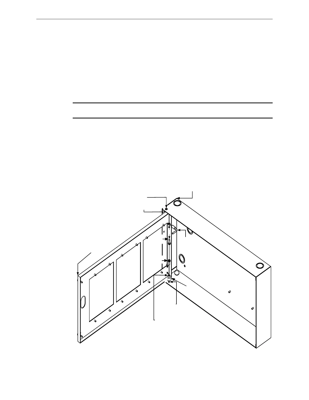
2.5.5.1 Cabinet A or AA, 3-Bay, Inner Door to the Backbox Installation
1. Place the nylon spacer (#10) over the backbox bottom hinge pin as shown in Location 1 of the
figure below.
2. Mount the inner door to the backbox by sliding the inner door, top hinge pin hole onto the
backbox top hinge pin as shown in Location 2.
3. Align the inner door bottom hinge pin hole with the backbox bottom hinge pin.
4. Slide the door over the inner door bottom hinge pin hole on top of the nylon spacer, and secure
using the #8 x .5” screw as shown in Location 2 of the figure below.
5. After the inner door is secured in place, attach the one end of the bonding wire to the top hinge
pin using the #8 x .5” screw as shown in Location 3 of the figure below.
NOTE: For information on the installation of the opposite end of the bonding wire, see Section
2.5.5.2, Step 3 and Location 4 of Figure 2.5.5.2.1.
Figure 2.5.5.1.1 Cabinet A or AA, 3-Bay Backbox Sub-Assembly Installation
CABINET A or AA,
3-BAY BACKBOX
BACKBOX TOP
HINGE PIN
INNER DOOR TOP
HINGE PIN HOLE
2
BONDING
WIRE
CABINET A or
AA, 3-BAY,
INNER DOOR
N
Y
L
O
N
S
P
A
C
E
R
#
1
0
BACKBOX
BOTTOM
HINGE PIN
INNER DOOR
BOTTOM
HINGE PIN HOLE
SCREW
#8 x .5"
SCREW
#8 x .5"
1
3
2
3
2

 Loading...


