34 E3 Series Installation/Operation Manual — P/N 9000-0574:I 11/04/10
Installation Cabinets
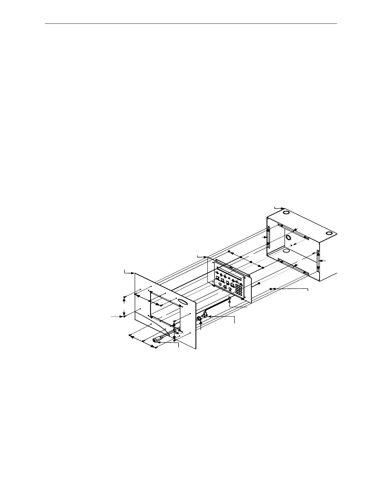
2.5.3.2 E3BB-FLUSH-LCD, CAB A2, Remote Flush Annunciator to the
Backbox Installation
1. Mount the keyswitch to the E3BB-FLUSH-LCD Flush Mount Front Cover and secure with
one (1), nut (3/4-24 THD Hex) as shown in Location 1 of Figure 2.5.3.2.1.
2. Attach the keyswitch cable to the key as shown in Location 2 of Figure 2.5.3.2.1.
3. Mount the LCD-E3 keypad to the E3BB-FLUSH-LCD Flush Mount Front Cover and secure
with eight (8), nuts (#6-32, Hex Keps) in the eight-hole mounting pattern as shown in Location
3 of Figure 2.5.3.2.1.
4. Plug-in the P2 keyswitch cable to the W2 terminal on the LCD-E3 display panel as shown in
Location 4 of Figure 2.5.3.2.1.
(For information on the location of the P2 and W2 terminal on the LCD-E3 panel, refer to
Note 1 on the LCD-E3 Wiring Diagram in Figure 3.13.4.1 of Section 3.14.4).
5. To connect the LCD-E3 panel wiring on TB1, refer to TB1 in Figure 3.13.4.1 (LCD-E3 Wiring
Diagram) in Section 3.14.4.
6. Attach the E3BB-FLUSH-LCD Flush Mount Front Cover to the Backbox and secure with
eight (8), screws (#6-32 x 3/8” PHBHD, BLK) in the eight-hole mounting pattern as shown in
Location 5 of Figure 2.5.3.2.1.
Figure 2.5.3.2.1 E3BB-FLUSH-LCD, CAB A2, Remote Flush Annunciator Backbox
Installation
LCD-E3
BACKBOX
1
2
3
4
5
KEYSW ITCH
KEYSW ITCH
CA BLE
NUT,
¾ ” -24
THD HEX
1
P2, KEYSW ITCH
CABLE (2 IN RT.
ANGLE HEADER)
NUT, (#6-32) HEX
KEPS (8 PLACES)
SCR EW,
(#6-32 x 3/8")
BHBHD, BLK
(8 PLACES)
3
3
3
5
5
5
5
5
5
5

 Loading...


