154 E3 Series Installation/Operation Manual — P/N 9000-0574:I 11/04/10
E3 Series System Connections Repeater (RPT-E3) Connections
3.11.5 Repeater-E3 Wiring Connections
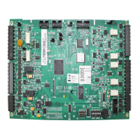
Table 3.11.5.1 lists the field wiring connections for the RPT-E3.
Designation Description Comments
TB1-1 ARCNET PORT 1A Broadband Network (See Note 1)
TB1-2 ARCNET PORT 1B Broadband Network (See Note 1)
TB1-3 ARCNET PORT 2A Broadband Network (See Note 1)
TB1-4 ARCNET PORT 2B Broadband Network (See Note 1)
TB2 Earth Ground Local Differential ARCNET (See Note 2)
TB3-1 COM A IN Local Differential ARCNET (See Note 3)
TB3-2 COM B IN Local Differential ARCNET (See Note 3)
TB3-3 COM A OUT Local Differential ARCNET. Connect to NGA TB1-3. (See Note 3)
TB3-4 COM B OUT Local Differential ARCNET. Connect to NGA TB1-4. (See Note 3)
TB4-1 + 24V IN Do not use, if J10 is used.
(+24 VDC IN from TB3-6 ILI-MB-E3/ILI95-MB-E3/ANX)
TB4-2 Common – IN Do not use, if J10 is used.
(-GND IN from TB3-7 ILI-MB-E3/ILI95-MB-E3/ANX)
TB4-3 + 24 V OUT Do not use, if J10 is used.
TB4-4 Common – OUT Do not use, if J10 is used.
J10 ARCNET Connector to ILI-MB-E3 or ILI95-MB-E3 (See Note 4)
U5 Fiber Port 2 IN (See Note 5)
U7 Fiber Port 2 OUT (See Note 5)
U4 Fiber Port 1 IN (See Note 5)
U6 Fiber Port 1 OUT (See Note 5)
J1 ARCNET Term Short when using the Local Differential ARCNET wiring to Terminal TB3. This
is the last device on the local net.
Note: If the first and last devices are SHORT, then the device between the two
must be OPEN. If the ILI-E3, ILI95-E3 Series or ANX is the first device and
the NGA is the last device, then the RPT-E3 or J1 would be OPEN.
J2 GFI Short to enable Ground Fault Detection on the ARCNET Network when using
copper wiring.
J3 GND FLT Short to enable Ground Fault Detection when remotely connected to a Listed
power source that does not provide earth detection.
OPEN when connected to the DC power supplied from an ILI-MB-E3,
ILI95-MB-E3, ANX, PM-9/PM-9G or INI-7100.
J4 Transmitter Light
Output Control
Comm port 1 fiber-optic transmitter drive current
Jumper contributes to drive current when SHORT.
Contributes 12.5% of maximum drive
J4, J5 & J6 OPEN - minimum drive, 12.5% of maximum.
J4, J5 & J6 SHORT - maximum drive, 100%
To match drive used on INI boards: SHORT J4, J5 and J6.
J5 Transmitter Light
Output Control
Comm port 1 fiber-optic transmitter drive current
Jumper contributes to drive current when SHORT.
Contributes 25% of maximum drive
J4, J5 & J6 OPEN - minimum drive, 12.5% of maximum.
J4, J5 & J6 SHORT - maximum drive, 100%
To match drive used on INI boards: SHORT J4, J5 and J6.
Table 3.11.5.1 Repeater-E3 Wiring Connections

 Loading...


