68 E3 Series Installation/Operation Manual — P/N 9000-0574:I 11/04/10
Installation Cabinets
2.5.9.2 Cabinet C, E3-INCC-C Plate Installation
1. Mount the ILI-MB-E3/ILI95-MB-E3/ANX over the standoffs on the E3-INCC-C plate and
secure by inserting eight (8), standoffs, (3/16” hex, #4-40 x 1”) in the eight-hole mounting
pattern as shown in Location 1 of Figure 2.5.9.2.2.
2. Mount the DACT-E3 and the RPT-E3 on top of the ILI-MB-E3/ILI95-MB-E3/ANX and secure
with eight (8), screws (#4-40 x 1/4”) into the eight (8), standoffs as shown in Location 2 of
Figure 2.5.9.2.2.
3. Mount the PM-9/PM-9G over the standoffs on the E3-INCC-C plate and secure with six (6),
screws (#4-40 x .1/4”) in the six-hole mounting pattern as shown in Location 3 of
Figure 2.5.9.2.2.
4. Mount the INI-VG over the standoffs on the E3-INCC-C plate and secure with six (6), screws
(#4-40 x .1/4”) in the six-hole mounting pattern as shown in Location 4 of Figure 2.5.9.2.2
.
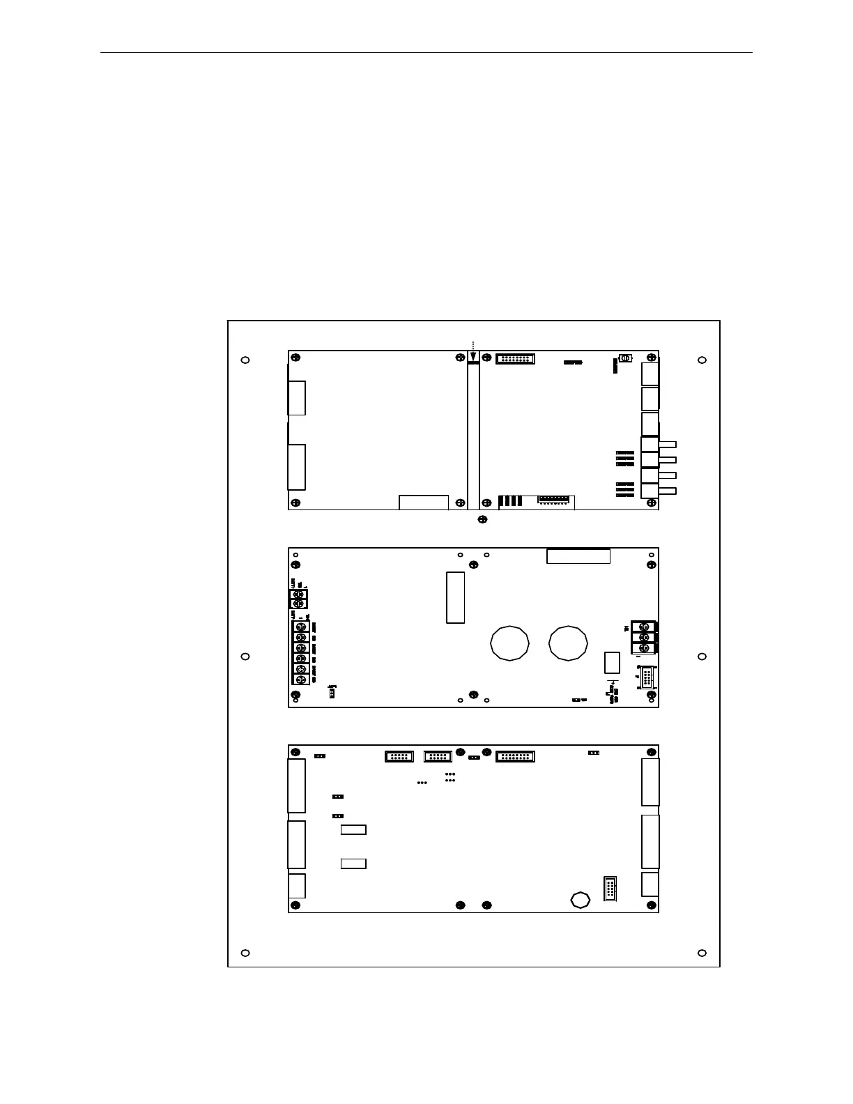
Figure 2.5.9.2.1 Cabinet C, E3-INCC-C Plate (Standard View)
INI-VG SERIES
PM-9/PM-9G
DACT-E3 RPT-E3
ILI-MB-E3/ILI95-MB-E3/ANX
PM-9G PCB

 Loading...


