E3 Series Installation/Operation Manual — P/N 9000-0574:I 11/04/10 11
System Components System Overview
1.2.1 Optional Features
• Remote DACT-E3 Digital Alarm Communicator Transmitter
• RPT-E3 ARCNET Repeater
• Remote ANU-48 Remote LED Driver
• Remote ASM-16 Addressable Switch Sub-assembly
• Remote Network Graphic Display
• LCD-7100 Remote LCD Display
1.3 System Components
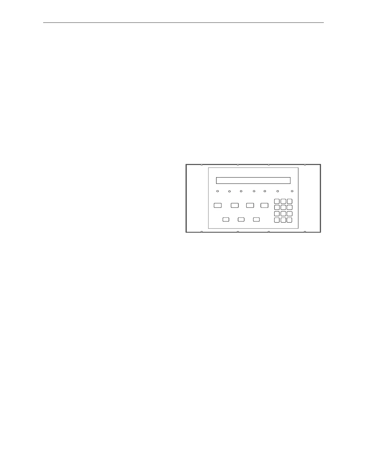
1.3.1 Control and Indicator Sub-Assembly (LCD-E3)
The LCD-E3 provides an LCD display
for system status, and the following
Switches and LED indicators:
• Alarm Acknowledge
• Trouble Acknowledge
• Signal Silence
• System Reset/Lamp test
• Programming buttons
– Menu/Back
– Back Space/Edit
– OK
• 12 button keypad
Figure 1.3.1.1 Switch Control Panel
The ILI-MB-E3 or ILI95-MB-E3 can support up to six (6), LCD-E3 sub-assemblies, any or all of
which may be remotely located via the local RS-485 serial interface.
LED Indicators
• AC Power On
(green)
• Power Fault
(yellow)
• Alarm
(red)
•
Ground Fault
(yellow)
• Supervisory
(yellow)
• System Silenced
(yellow)
•
System Trouble
(yellow)
AC P O WER
ON
POW E R
FAULT
GR O UND
FAULT
ALARM SYS TE M
TROUBL E
SUPERVIS ORY S Y STEM
SILE N C E D
ME NU
ABC
2
MNO
6
_.
-Q Z
1
DEF
3
GH I
4
JK L
5
PRS
7
TUV
8
W X Y
9
< >
0
,
BACKSP A C E /
EDIT
ALARM
ACKNO W LE DGE
TROUBLE
ACKNO W LE DGE
SIG NA L
SILE N C E
SYSTEM RESET/
LAMP TEST
OK/
ENTER

 Loading...


