172 E3 Series Installation/Operation Manual — P/N 9000-0574:I 11/04/10
Section 4: Programming/Operation Instructions
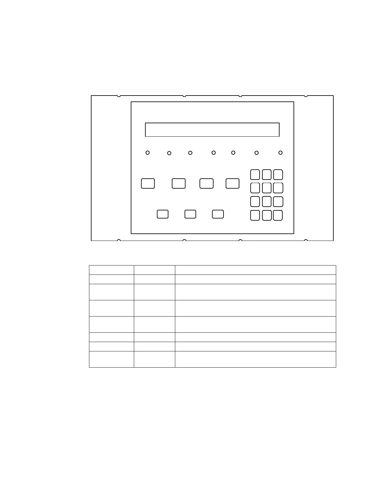
4.1 LED Indicators (LCD-E3)
Figure 4.1.1 illustrates the LED indicators. Table 4.1.1 lists the LCD-E3 indicators and a
description.
Figure 4.1.1 LCD-E3 LED Indicators
AC POWER
ON
POWER
FAULT
GROUND
FAULT
ALARM SYSTEM
TROUBLE
SUPERVISORY SYSTEM
SILENCED
ALARM
ACKNOWLEDGE
TROUBLE
ACKNOWLEDGE
SIGNAL
SILENCE
SYSTEM RESET/
LAMP TEST
MENU BACKSPACE/
EDIT
OK/
ENTER
ABC
2
MNO
6
.
-QZ
1
DEF
3
GHI
4
JKL
5
PRS
7
TUV
8
WXY
9
< >
0
_ ,
Designation Description Comments
AC Power On (green) Lights to indicate the presence of 120 VAC input.
Alarm (red) Lights when system is in alarm, flashes until alarm is
acknowledged.
Supervisory (yellow) Lights when supervisory condition exists, flashes until trouble
acknowledge is performed.
System Trouble (yellow) Lights to indicate trouble condition, flashes until trouble is
acknowledged.
Power Fault (yellow) Lights during a LOW or NO Battery condition.
Ground Fault (yellow) Lights to indicate a ground on a field conductor.
System Silenced (yellow) Lights when a System Silence has been pressed.
Flashes when system silence is pending.
Table 4.1.1 LCD-E3 LED Indicators

 Loading...


