16 E3 Series Installation/Operation Manual — P/N 9000-0574:I 11/04/10
System Overview Specifications
1.5 Specifications
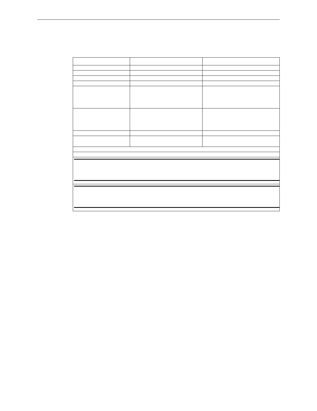
1.5.1 Power Supply (PM-9/PM-9G)
The following are the specifications for the PM-9 and PM-9G power supply sub-assemblies.
1.5.2 Signaling Line Circuits (ILI-E3 or ILI95-E3 Series)
• Two (2), Class “A”, Style 6, 7,* or Class “B” Style 4 circuits
• 24 VDC nominal
• Power-limited
• Supervised
• 40 Ohm max. line impedance
• 0.5 µf max. capacitance
• Capacity of 159 analog sensors and 159 addressable devices per circuit (ILI-MB-E3 or
ILI-S-E3)
• Capacity of 126 sensors/modules per circuit (ILI95-MB-E3 or ILI95-S-E3)
*Style 7 operation requires System Sensor, M500X Isolator Module (ILI-MB-E3 or ILI-S-E3) or
XP95-LI Line Isolator and XP95-LIB Line Isolator Base (ILI95-MB-E3 or ILI95-S-E3).
Refer to the Compatibility Addendum to Gamewell-FCI Manuals, P/N 9000-0427, Section 1 for a
list of UL Listed, compatible sensors/modules.
Specifications PM-9 PM-9G
Input Voltage: 120 VAC, 60 Hz 240 VAC @ 50/60 Hz
Input Current: 4.6 amps max. @ 120 VAC 60 Hz 2.4 amps max.
Output Voltage: 24 VDC FWR 24 VDC FWR
Output Current: 9 amperes Alarm max. continuous 9 amperes Alarm max. continuous
Output Current: 5 amperes max. continuous
Standby (when the PM-9 is used
with the ILI-E3 or the ILI95-E3
Series) (See Note 1)
5 amperes max. continuous Standby
(when the PM-9G is used with the
ILI-E3 or the ILI95-E3 Series)
(See Note 1)
Output Current 4 amperes max. continuous
Standby (when the PM-9 is used
with any AM-50 Series amplifier)
(See Note 2)
4 amperes max. continuous Standby
(when the PM-9G is used with any
AM-50 Series amplifier) (See Note 2)
Operating Temperature: 32° to 120° F (0° to 49° C) 32° to 120° F (0° to 49° C)
Relative Humidity: 0 to 93%, non-condensing at 90° F
(32° C)
0 to 93%, non-condensing at 90° F
(32° C)
Supervised
Non Power-Limited
NOTE 1: Continuous standby loads in excess of .560 Amps up to 5 Amps may require a
Generator Backup or load shedding during an AC power failure. See Section 3.15 (Standby
Battery Calculations Chart) in this Manual.
NOTE 2: Continuous standby loads in excess of .560 Amps up to 4 Amps may require a
Generator Backup or load shedding during an AC power failure. See Section 3.15 (Standby
Battery Calculations Chart) in this Manual.
Table 1.5.1.1 PM-9/PM-9G Specifications

 Loading...


