142 E3 Series Installation/Operation Manual — P/N 9000-0574:I 11/04/10
E3 Series System Connections ASM-16 Addressable Switch Connections
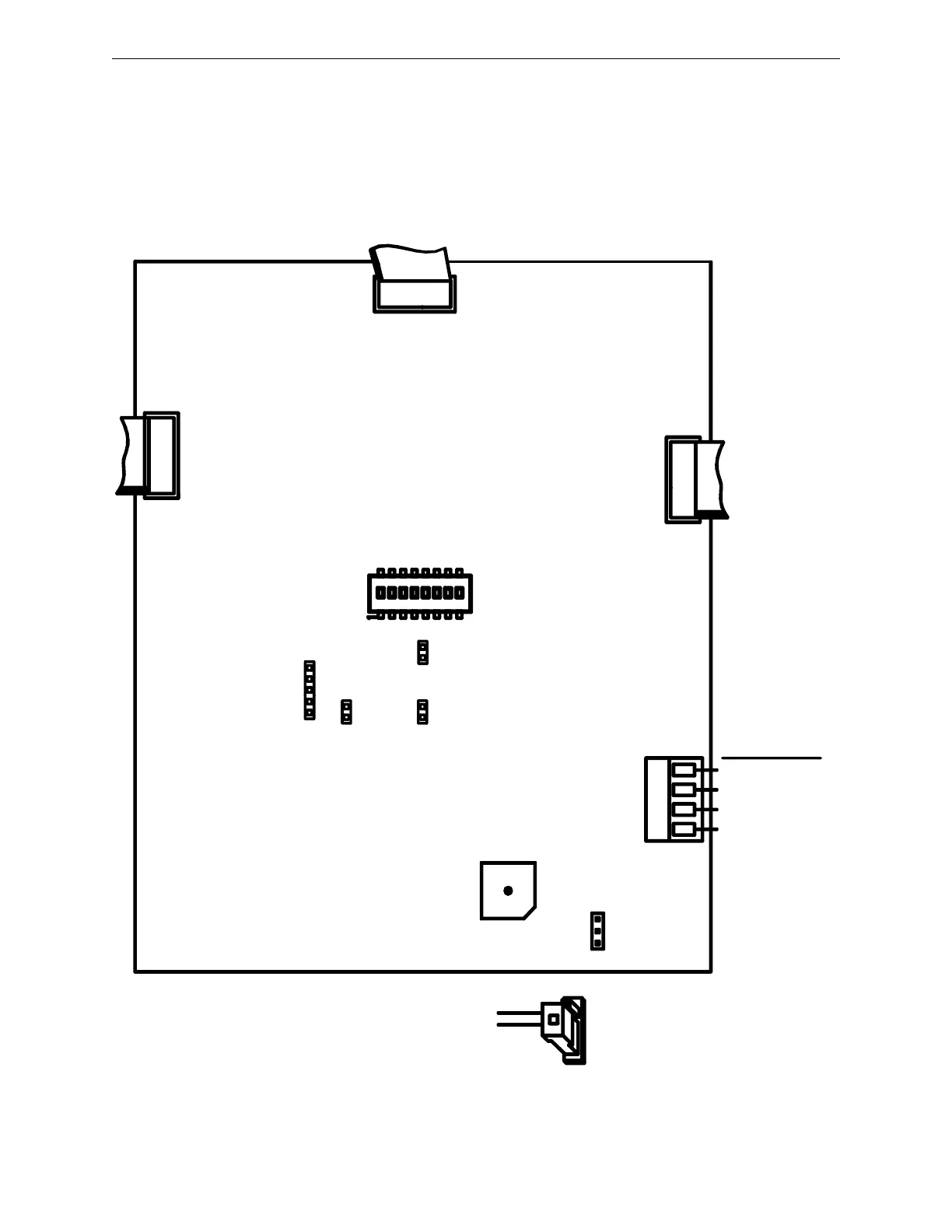
3.9.5 ASM-16 Wiring Diagram
Figure 3.9.5.1 illustrates the field wiring connections for the ASM-16.
Figure 3.9.5.1 ASM-16 Wiring Diagram
14 3 2
1
4
REMOTE
2
1
10
9
1
2
J1
9
REAR SIDE VIEW
JMP4
9
2
1
2 3 4 5 6 7 8
SW1
ON
1
J1, J2 AND J3 ARE RS-485 RIBBON CABLE
“IN” AND/OR “OUT” CONNECTIONS
TO NEXT/PREVIOUS MODULE
(NOTE POSITION PIN 1)
JMP4
REMOVE SHUNT AND
PLACE SA-C CONNECTOR
FOR EXTERNAL SOUNDER
J3 RS-485 PORT
CONNECTIONS
- ANU-48 OR J2
- ASM-16 J1, J2, OR
J3, AND
- INI-VG SERIES J3
J2 RS-485 PORT
CONNECTORS
- ANU-48 J1 OR J2
- ASM-16 J1, J2 OR
J3, AND
- INI-VG SERIES J3
TB1 RS-485 PORT
CONNECTS TO THE
INI-VG SERIES
JMP1
J1 RS-485 PORT
CONNECTIONS
- ANU-48 J1 OR J2
- ASM-16 J1, J2, OR
J3, AND
- INI-VG SERIES J3
SYSTEM GND (-)
24 VDC (+)
RS-485 COM B
RS-485 COM A
TB1
TO INI-VG
4 TO TB6-4
3 TO TB6-1
2 TO TB6-2
1 TO TB6-3
J3
10
10
J2
JMP3 JMP2
J5
FACTORY
USE ONLY

 Loading...


