E3 Series Installation/Operation Manual — P/N 9000-0574:I 11/04/10 45
Cabinets Installation
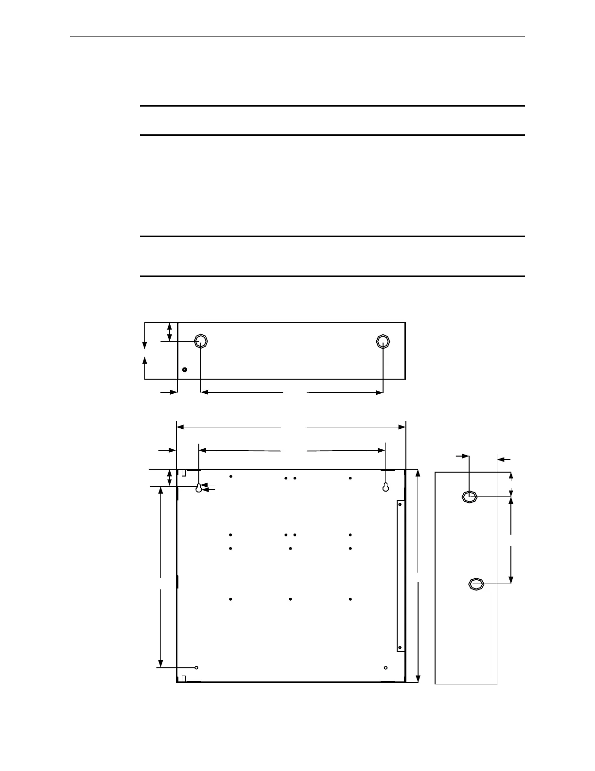
2.5.6.1 Cabinet B, Backbox Installation
1. Prepare the mounting site by pre-drilling four (4), #10 screws, using the dimensions shown in
figure below. Use four (4), #10 screws.
NOTE: If the fasteners are anchored to wallboard, use #10 wall anchors. Mountings to concrete
walls should be backed by plywood to insulate the equipment from possible condensation.
2. Secure with two (2), #10 screws in the two-hole mounting pattern as shown in Locations 1 and
2 of the figure below.
3. Set the backbox over the top, two-hole mounting pattern, and hang the backbox over the two
screw heads.
4. Insert and secure two (2), #10 screws in the two-hole mounting pattern as shown in Locations
3 and 4 of the figure below.
NOTE: Add knockouts to the left and right side of the rear panel of the backbox. Do not add
knockouts in the center or top of the backbox, above the ILI-MB-E3/ILI95-MB-E3, behind or below
the batteries. To add larger knockouts, increase the size of the existing knockouts.
Figure 2.5.6.1.1 Cabinet B, Backbox Installation
16.00"
19.38"
16.69"
BACKBOX TOP
BACKBOX
SIDE PANEL
BACKBOX
19 3/8"
1.50"
16.38"
1.25"
1.50"
BACKBOX DEPTH = 4.50"
1.35"
1
2
3 4
.25"
.50"
3.38"
2.25"
4.50"

 Loading...


