20 E3 Series Installation/Operation Manual — P/N 9000-0574:I 11/04/10
Installation Cabinets
2.5 Cabinets
The E3 control panel may be assembled in various cabinet configurations to suit the installation.
Typical arrangements are shown. The following are the cabinet options:
• Cabinets A1 and A2
• Cabinet A (remote)
• Cabinet B
• Cabinet C
• Cabinet D
• B-Slim Cabinet
E3 Inner Door Bonding Strap
2.5.1 Cabinet A1, Installation Instructions
The E3 Series
®
Cabinet A1, assembly typically includes the following:
• Backbox
– Cabinet A1, Trim Rings (Optional Accessory)
• Outer Door
• Inner Door:
– unit
• Hardware Kit
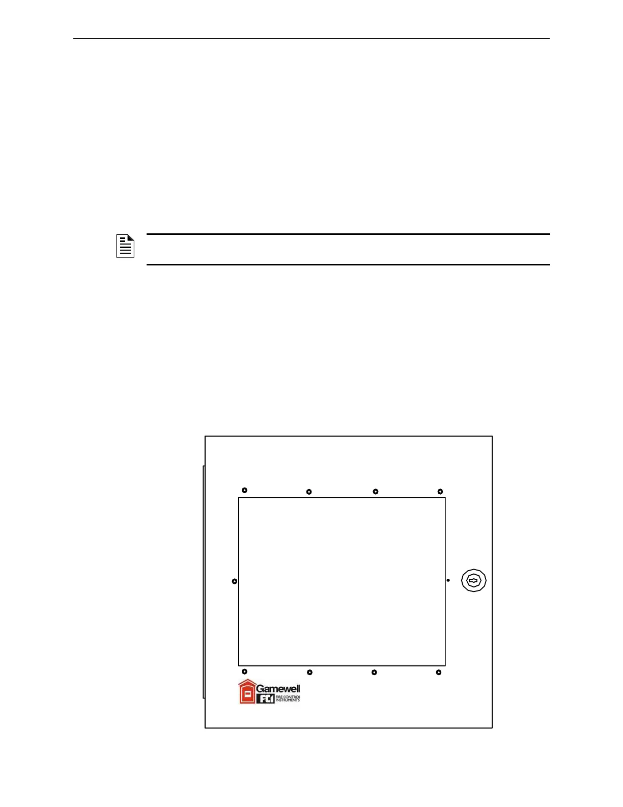
Figure 2.5.1.1 Cabinet A1, (Standard View)
NOTE: Electrical continuity for grounding of the inner door of the cabinets is ensured by a bonding
wire.

 Loading...


