132 E3 Series Installation/Operation Manual — P/N 9000-0574:I 11/04/10
E3 Series System Connections PM-9/PM-9G Power Supply Connections
3.8.5 PM-9 Power Supply Wiring Connections
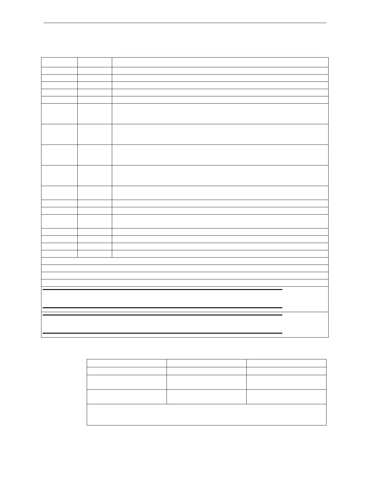
Table 3.8.5.1 lists the field wiring connection to the PM-9 Power Supply.
Table 3.8.5.2 lists the details for the Ground Fault supervision and settings.
Designation Description Comments
TB1-1 HOT/BLK Connect to hot, 120VAC, 60Hz - Non Power-limited
TB1-2 GND/GRN Connect to ground and isolated earth ground - Non Power-limited
TB1-3 NEUT/WHT Connect to neutral 120VAC, 60Hz
TB3-1 BATT+ Battery positive input - Non Power-limited
TB3-2 BATT - Battery negative input - Non Power-limited
TB4-1 24VOUT +24 VDC FWR Output to AM-50 Series amplifiers, ILI95-E3/ILI-E3 Series or
ANX, TB1-2: used to power two (2), AM-50 Series amplifiers, the
ILI95-E3/ILI-E3 Series or ANX
TB4-2 GND GND (-) Output to AM-50 Series amplifiers, ILI95-E3/ILI-E3 Series or ANX,
TB1-1: used to power two (2), AM-50 Series amplifiers, the ILI95-E3/ILI-E3
Series or ANX
TB4-3 24VOUT +24 VDC FWR Output to AM-50 Series amplifiers, ILI95-E3/ILI-E3 Series or
ANX, TB1-2: used to power 2nd pair of AM-50 Series amplifiers, ILI95-E3/ILI-E3
Series, ANX and INI-VG
TB4-4 GND GND (-) Output to AM-50 Series amplifiers, ILI95-E3/ILI-E3 Series or ANX:
TB1-1: to second pair of AM-50 Series amplifiers, ILI95-E3/ILI-E3 Series, ANX,
INI-VGC
TB4-5 24VOUT +24 VDC FWR Output to other sub-assemblies: INI-VG, ILI95-E3/ILI-E3 Series or
ANX
TB4-6 GND GND (-) Output to INI-VG, ILI95-E3/ILI-E3 Series or ANX
JMP1 IN for GND Fault Detection (See Note 1)
J1 10-PIN Ribbon Cable Connect to the ILI95-MB-E3, ILI-MB-E3 or ANX Connector
J1, or INI-VG Connector J4 (See Note 2)
JMP2 Factory Use Only.
LED 2 Green Lights to indicate AC power
LED 3 Yellow Lights to indicate no or low battery fault
LED 4 Yellow Lights to indicate ground fault
NOTE: AC “Brown Out” condition indicated by:
LED 2 (grn) OFF
LED 3 (yel) LIT
LED 4 (yel) LIT
NOTE 1: Must be IN (Enabled) when J1 is connected to an INI-VG Series node. Must be OUT (Disabled) when J1 is
connected to an ILI-MB-E3 or an ILI95-MB-E3 node.
NOTE 2: Connect J1 to the INI-VG Series J4 when the PM-9 is supplying power to both the INI-VG Series and the
ILI-MB-E3 or the ILI95-MB-E3 node types (See Note 1).
Table 3.8.5.1 PM-9 Terminals, Jumpers and LEDs
Designation Description Comments
Ground Fault Supervision Jumper Settings CAMWorks Settings
ILI-MB-E3/ILI95-MB-E3/ANX W9 shorted on ILI,
JMP1 Open on PM-9
ILI Supervision of PM-9 enabled.
INI-VGX JMP1 shorted on PM-9,
W9 Open on ILI
VGX Supervision of PM-9
enabled
Only one node connected to a PM-9 (by Ribbon Cable) must have "Supervision of the PM-9"
Enabled in CAMWorks. All additional Nodes powered from a common PM-9 are to have their
Ground Fault jumpers open or disabled and the supervision of the PM-9 disabled in CAMWorks.
Table 3.8.5.2 Ground Fault Supervision

 Loading...


