E3 Series Installation/Operation Manual — P/N 9000-0574:I 11/04/10 91
Cabinets Installation
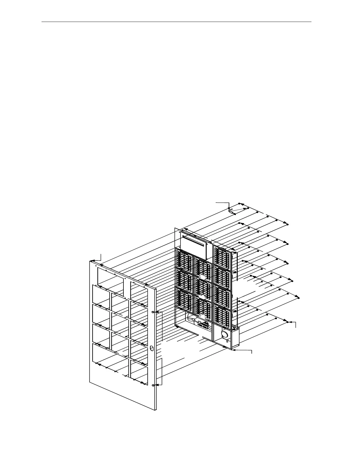
2.5.10.8 Cabinet D, 13-Bay Inner Door Installation
1. Mount the first, top row of the LCD-E3/ASM-16s sub-assemblies to the 13-bay inner door and
secure with six (6), #6-32 nuts as shown in Location 1 of the figure below.
2. Interlock the first, bottom row of the LCD-E3/ASM-16s with the second, top row of the ASM-
16 sub-assemblies. Mount the units to the 13-bay inner door by securing six (6), #6-32 nuts as
shown in Location 2 of the figure below.
3. Interlock the second, bottom row of the second set of ASM-16 sub-assemblies with the third,
top row of the third set of ASM-16 sub-assemblies. Mount the units to the 13-bay inner door
by securing six (6), #6-32 nuts as shown in Location 3 of the figure below.
4. Interlock the third, bottom row of the third set of ASM-16 sub-assemblies with the fourth, top
row of the fourth set of ASM-16 sub-assemblies. Mount the units to the 13-bay inner door by
securing six (6), #6-32 nuts as shown in Location 4 of the figure below.
5. Interlock the fourth, bottom row of the fourth set of ASM-16 sub-assemblies with the fifth, top
row of the telephone and microphone box. Mount the units to the 13-bay inner door by
securing six (6), #6-32 nuts as shown in Location 5 of the figure below.
6. Mount the fifth, bottom row of the telephone and microphone box to the 13-bay inner door by
securing six (6), #6-32 nuts as shown in Location 6 of the figure below.
7. Secure the opposite end of the bonding wire to the welded #6 stud on the inner side of the inner
door using the #6 nut as shown in Location 7 of the figure below.
8. After the panel is wired, use the thumbscrews to secure the inner door to the backbox as shown
in Location 8 of the figure below.
Figure 2.5.10.8.1 Cabinet D, 13-Bay Inner Door Installation
L
C
D
-
E
3
D
I
S
P
L
A
Y
T
E
L
E
P
H
O
N
E
B
O
X
M IC R O P H O N E
B O X
1
1
2
2
3
4
5
3
1
2
3
4
5
6
6
A S M -1 6 ,
1 0 P L A C E S
M A X .
N U T , H E X
(# 6 -3 2 )
M A X .
4
5
6
B O N D IN G
W IR E
T H U M B S C R E W S
T O S E C U R E T H E
IN N E R D O O R T O
T H E B A C K B O X
8
8
7
7

 Loading...


