54 E3 Series Installation/Operation Manual — P/N 9000-0574:I 11/04/10
Installation Cabinets
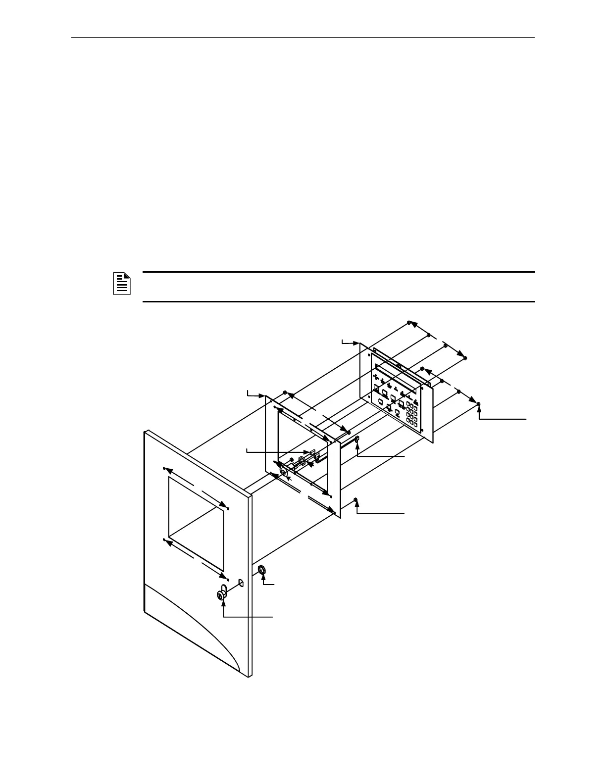
2.5.7.2 LCD-E3 Mounting Plate to the Outer Door Installation
1. Insert the keyswitch to the LCD-E3 Mounting Plate and secure with one (1) nut, (3/4” x 24
THD HEX) as shown in Location 1 of Figure 2.5.7.2.1.
2. Attach the keywitch cable to the key as shown in Location 2 of Figure 2.5.7.2.1.
3. Mount the LCD-E3 keypad to the LCD-E3 Mounting Plate and secure the eight (8), nuts (#6-
32 HEX KEPS) in the eight-hole mounting pattern as shown in Location 3 of Figure 2.5.7.2.1.
4. Plug-in the P2, keyswitch cable to the W2 terminal on the LCD-E3 panel as shown in Location
4 of Figure 2.5.7.2.1.
(For information on the location of the P2 and W2 terminal on the LCD-E3 panel, refer to Note
1 on the LCD-E3 Wiring Diagram in Figure 3.13.4.1 of Section 3.14.4).
5. Mount the LCD-E3 Mounting Plate to the Outer Door and secure the four (4), nuts (#6-32,
HEX KEP) in the four-hole mounting pattern as shown in Location 5 of Figure 2.5.7.2.1.
6. Install the keylock, PK625 to the Outer Door and secure with one (1) nut, (3/4” x 24 THD
HEX) as shown in Location 6 of Figure 2.5.7.2.1.
Figure 2.5.7.2.1 LCD-E3 Mounting Plate to the Outer Door Installation
NOTE: For additional information on the LCD-E3 sub-assembly installation, refer to the LCD-E3
Installation Instructions, P/N 9000-0582.
LCD-E3
KEYLOCK,
PK625
NUT,
(¾” x 24 THD HEX)
2 PLACES
(KEYLOCK AND KEYSWITCH)
5
KEYSWITCH
CABLE
P2, KEYSWITCH CABLE
(2 PIN RT.ANGLE HEADER)
(NOTE: ATTACH TO W2 ON
THE LCD-E3 PANEL).
NUT, #6-32,
HEX KEPS
4 PLACES
HEX KEPS
8 PLACES
3
3
3
6
6
2
4
5
5
5
1
3
1

 Loading...


