82 E3 Series Installation/Operation Manual — P/N 9000-0574:I 11/04/10
Installation Cabinets
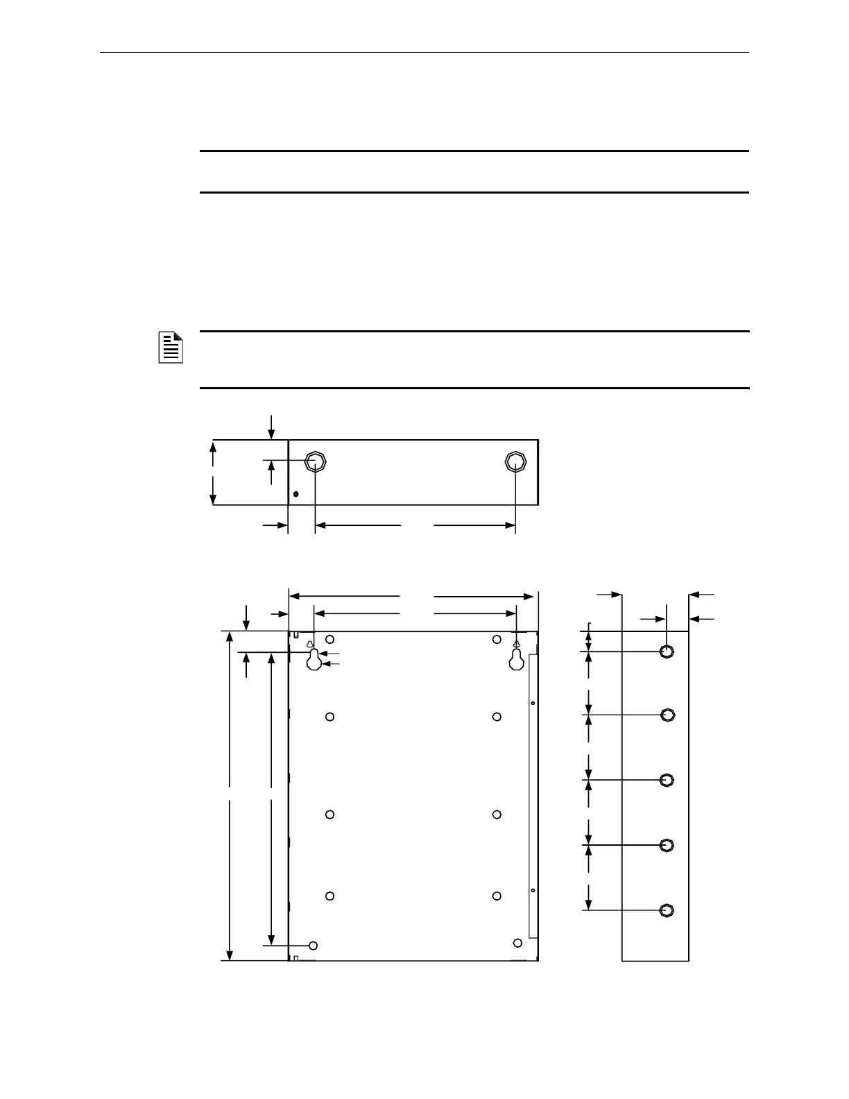
2.5.10.1 Cabinet D, Plexiglass and INX Door Backbox Installation
1. Prepare the mounting site by pre-drilling four (4), #10 screws mounted to the studs, using the
dimensions shown in the figure below. Use four (4), #10 screws.
NOTE: If the fasteners are anchored to a wallboard, use #10 wall anchors.Mountings to concrete
walls should be backed by plywood to insulate the equipment from possible condensation.
2. Secure with two (2), #10 screws in the two-hole mounting pattern as shown in Locations 1 and
2 of the figure below.
3. Set the backbox over the top, two-hole mounting pattern, and hang the backbox on the two
screw heads.
4. Insert and secure two (2), #10 screws in the two-hole mounting pattern as shown in Locations
3 and 4 of the figure below.
Figure 2.5.10.1.1 Cabinet D, INX Door Backbox Installation
NOTE: Add knockouts to the left and right side of the rear panel of the backbox. Do not add
knockouts in the center or top of the backbox, above the ILI-MB-E3/ILI95-MB-E3/ANX, behind or
below the batteries. To add larger knockouts, increase the size of the existing knockouts.
4.50"
BACKBOX TOP
1.25"
16.38"
BACKBOX DEPTH – 4.50"
1.50"
41.00"
BACKBOX
19.38"
38.31"
.25"
.50"
16.00"
1.35"
3.38"
1 2
3
4
1.70"
BACKBOX
SIDE PANEL
4.50"
2.25"
8.00"
8.00"
8.00"
8.00"

 Loading...


