E3 Series Installation/Operation Manual — P/N 9000-0574:I 11/04/10 37
Cabinets Installation
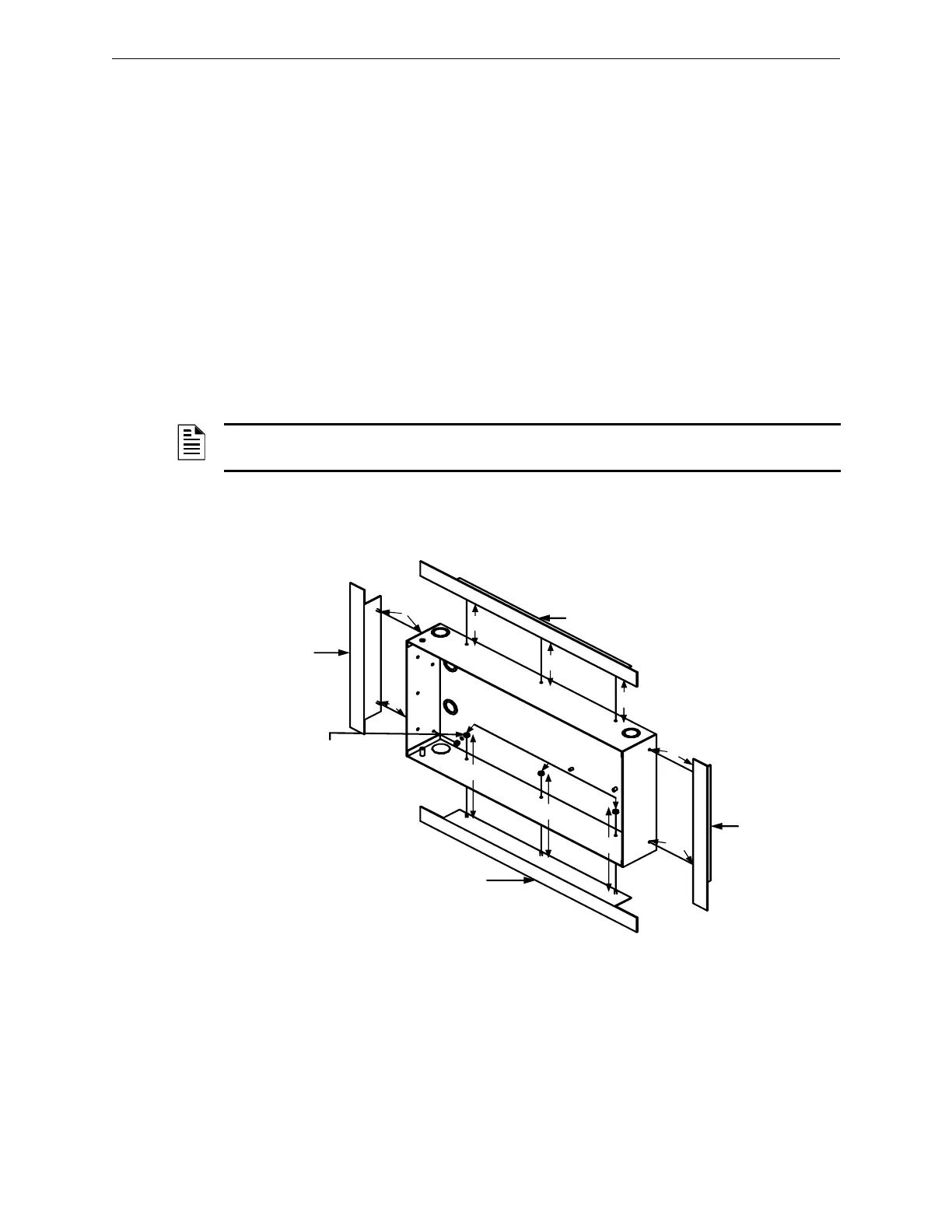
2.5.4.2 Cabinet A or AA, Trim Rings Installation (Optional Accessory)
1. Insert the Cabinet A, trim top ring over the top three-hole mounting pattern.
2. Secure with three (3), #6 Hex Kep nuts in the three-hole mounting pattern on the top of the
backbox as shown in Locations 1, 2 and 3 of the figure below.
3. Insert the Cabinet A, trim bottom ring on the bottom three-hole mounting pattern.
4. Secure with three (3), #6 Hex Kep nuts in the three-hole mounting pattern on the bottom of the
backbox as shown in Locations 4, 5 and 6 of the figure below.
5. Insert the Cabinet A, trim left ring on the left side of the two-hole mounting pattern.
6. Secure with two (2), #6 Hex Kep nuts in the two-hole mounting pattern on the left side of the
backbox as shown in Locations 7 and 8 of the figure below.
7. Insert the Cabinet A, trim right ring on the right side of the two-hole mounting pattern.
8. Secure with two (2), #6 Hex Kep nuts in the two-hole mounting pattern on the right side of the
backbox as shown in Locations 9 and 10 of the figure below.
For information on flush-mounting, refer to the E3 Series Cabinet Trim Rings Installation
Instructions P/N 9001-0058.
Figure 2.5.4.2.1 Cabinet A or AA, Trim Ring Installation
NOTE: Use the Trim Ring Hardware Kit provided. The trim top/bottom and trim left/right rings are
interchangeable.
NOTE:
#6 HEX,
KEPS NUTS,
(10 PLACES)
6
7
8
9
10
E3 Cabinet A
or AA, Top
Trim Ring
A or AA,
Ring
E3 Cabinet A or AA,
Bottom Trim Ring
1
2
3
4
5

 Loading...


