80 E3 Series Installation/Operation Manual — P/N 9000-0574:I 11/04/10
Installation Cabinets
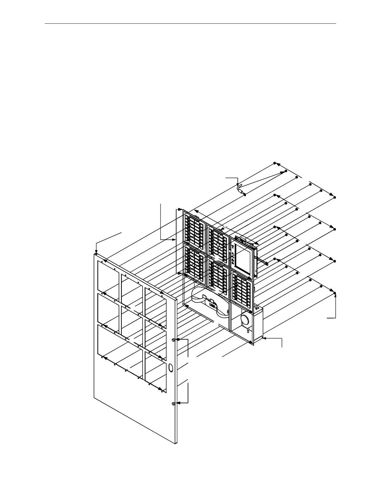
2.5.9.12 Cabinet C, INCC-E3, 7-Bay Inner Door Installation
1. Mount the first, top row of the ASM-16 and sub-assemblies to the INCC-E3, 7-bay inner door
and secure with six (6), #6-32 nuts as shown in Location 1 of the figure below.
2. Interlock the first, bottom row of the ASM-16 and with the second, top row of the ASM-16
sub-assemblies, and mount the units to the INCC-E3, 7-bay inner door by securing six (6), #6-
32 nuts as shown in Location 2 of the figure below.
3. Interlock the third, bottom row of the ASM-16 sub-assemblies with the fourth, top row of the
telephone and microphone box, and mount the units to the INCC-E3, 7-bay inner door by
securing six (6), #6-32 nuts as shown in Location 3 of the figure below.
4. Mount the fourth, bottom row of the telephone and microphone box to the INCC-E3, 7-bay
inner door by securing six (6), #6-32 nuts as shown in Location 4 of the figure below.
5. Secure the opposite end of the bonding wire to the welded #6 stud on the inner side of the inner
door using the #6 nut as shown in Location 5 of the figure below.
6. After the panel is wired, use the thumbscrews to secure the inner door to the backbox as shown
in Location 6 of the figure below.
Figure 2.5.9.12.1 Cabinet C, INCC-E3, 7-Bay Inner Door Installation
CABINET C, INCC-E3,
8-BAY INNER DOOR
1
2
3
4
(#6-32)
ASM-16
5 PLACES MAX.
NGA
BONDING
WIRE
MICROPHONE
BOX
T
E
L
E
P
H
O
N
E
B
O
X
1
1
2
3
4
2
3
4
THUMBSCREWS
TO SECURE THE
INNER DOOR TO
THE BACKBOX
5
5
6
6

 Loading...


