E3 Series Installation/Operation Manual — P/N 9000-0574:I 11/04/10 155
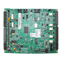
Repeater (RPT-E3) Connections E3 Series System Connections
Designation Description Comments
J6 Transmitter Light
Output Control
Comm port 1 fiber-optic transmitter drive current
Jumper contributes to drive current when SHORT.
Contributes 50% of maximum drive
J4, J5 & J6 OPEN - minimum drive, 12.5% of maximum.
J4, J5 & J6 SHORT - maximum drive, 100%
To match drive used on INI boards: SHORT J4, J5 and J6.
J7 Transmitter Light
Output Control
Comm port 1 fiber-optic transmitter drive current
Jumper contributes to drive current when SHORT.
Contributes 12.5% of maximum drive.
J7, J8 & J9 OPEN - minimum drive, 12.5% of maximum.
J7, J8 & J9 SHORT - maximum drive, 100%
To match drive used on INI boards: SHORT J7, J8 and J9.
J8 Transmitter Light
Output Control
Comm port 2 fiber-optic transmitter drive current
Jumper contributes to drive current when SHORT.
Contributes 25% of maximum drive.
J7, J8 & J9 OPEN - minimum drive, 12.5% of maximum.
J7, J8 & J9 SHORT - maximum drive, 100%
To match drive used on INI boards: SHORT J7, J8 and J9.
J9 Transmitter Light
Output Control
Comm port 2 fiber-optic transmitter drive current
Jumper contributes to drive current when SHORT.
Contributes 50% of maximum drive.
J7, J8 & J9 OPEN - minimum drive, 12.5% of maximum.
J7, J8 & J9 SHORT - maximum drive, 100%
To match drive used on INI boards: SHORT J7, J8 and J9.
NOTE 1: TB1 - RPT-E3 UTP Network Connections using unshielded, twisted-pair 18 AWG min. 3,000’
(914.4 m) maximum between the following nodes:
– RPT-E3 TB1-1 (COM1A) to: INI-7100 TB1-3 INI-VG TB1-3 or another RPT-E3 TB1-3
– RPT-E3 TB1-2 (COM1B) to: INI-7100 TB1-4 INI-VG TB1-4 or another RPT-E3 TB1-4
– RPT-E3 TB1-3 (COM2A) to: INI-7100 TB1-1 INI-VG TB1-1 or another RPT-E3 TB1-1
– RPT-E3 TB1-4 (COM2B) to: INI-7100 TB1-2 INI-VG TB1-2 or another RPT-E3 TB1-2
NOTE 2: TB2 must be used when the RPT-E3 is used remotely from a main system cabinet such as in a remote
network display. Connect to a local cold water earth or via an additional conductor connected to TB3-7 of the ILI-MB-
E3, ILI95-MB-E3 or ANX or Terminal TB4-4 of an INI-7100.
NOTE 3: Use TB3 (differential ARCNET) to connect an NGA to the RPT-E3
NOTE 4: When J10 is used to connect the RPT-E3 to the ILI-E3, ILI95-E3 Series or ANX, do not use TB4.
NOTE 5: U4, U5, U6 and U7 are omitted on the RPT-E3-UTP.
U5, U7, U4 & U6 - RPT-E3 FO Network Connections using standard ST connector fiber-optic cable, multi-mode, up to
200 u (optimized for 62.5/125 u). Signal loss up to 8 dB maximum between the following nodes:
– RPT-E3 U6 (TX1) to: INI-7100 J7 (RX2) INI-VG J8 (RX2) or another RPT-E3 U5 (RX2)
– RPT-E3 U4 (RX1) to: INI-7100 J6 (TX2) INI-VG J6 (TX2) or another RPT-E3 U7 (TX2)
– RPT-E3 U7 (TX2) to: INI-7100 J4 (RX1) INI-VG J5 (RX1) or another RPT-E3 U4 (RX1)
– RPT-E3 U5 (RX2) to: INI-7100 J1 (TX1) INI-VG J2 (TX1) or another RPT-E3 U6 (TX1)
Network Connections using fiber-optic cable (available on RPT-E3 FO only). The RPT-E3 FO can support both
unshielded, twisted pair and fiber-optic network connections.
Table 3.11.5.1 Repeater-E3 Wiring Connections (Continued)

 Loading...


