122 E3 Series Installation/Operation Manual — P/N 9000-0574:I 11/04/10
E3 Series System Connections Addressable Node Expander (ANX) Connections
3.7.7.1 ANX-MR-UTP Wiring Connections (Continued)
Table 3.7.7.1.2 lists the Primary and Secondary Ring Select Switch settings for the ANX-MR-UTP.
The Primary Ring Select Switch sets the network ring number for the Primary Network (uses J2,
J4, J5, and/or TB2).
The Secondary Ring Select Switch sets the network ring number for the Secondary Network (uses
TB4).
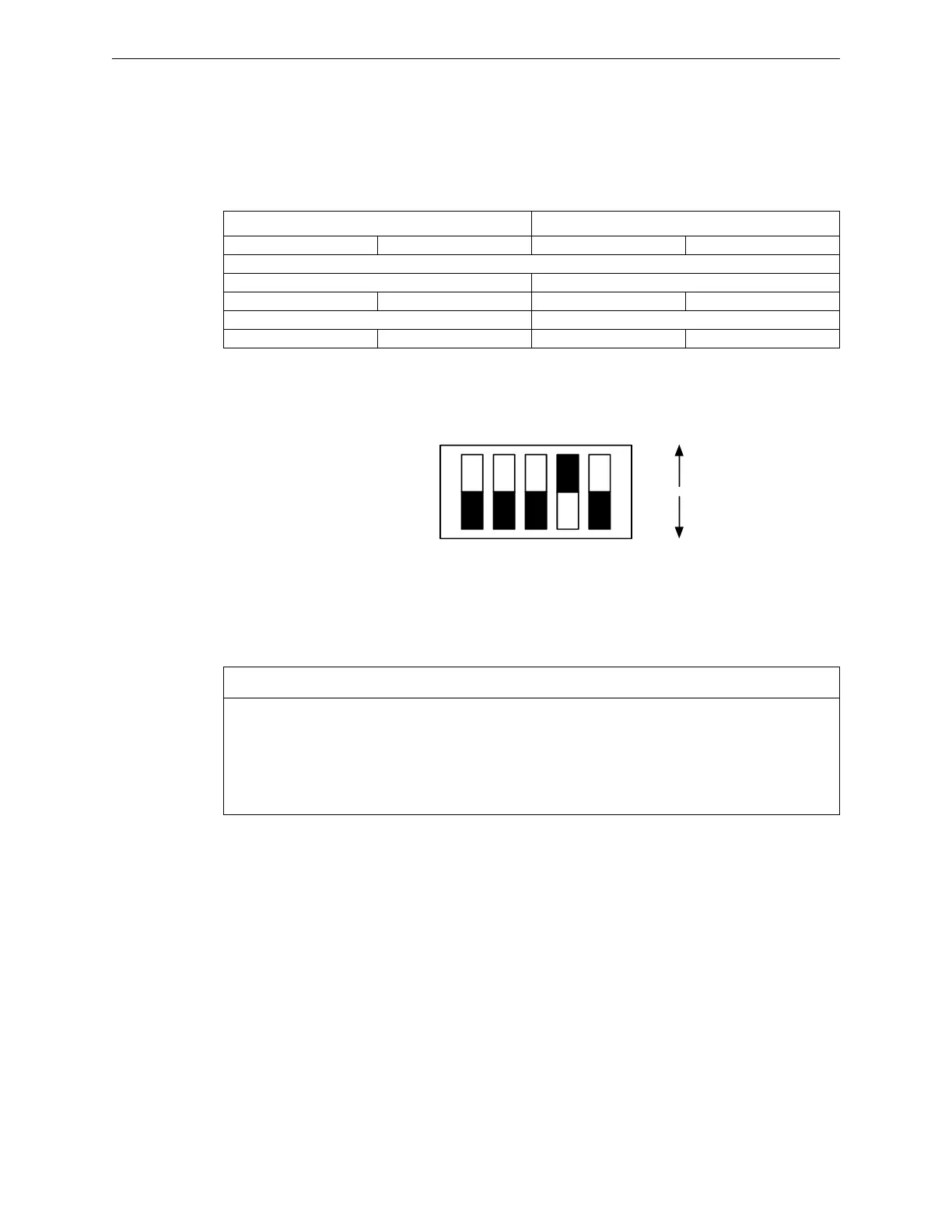
Figure 3.7.7.1.1 illustrates the SW2 switch setting for the ANX-MR-UTP.
Figure 3.7.7.1.1 ANX-MR-UTP, SW2 Switch Setting
Primary Ring Select Switch Secondary Ring Select Switch
SW2 POS 1 SW2 POS2 SW2 POS3 SW2 POS4
Ring 0 to Ring 1 Bridge
Ring 0 Node 63 Ring 1 Node 62 (126)
0 0 0 1
Ring 1 Node 62 (126) Ring 0 Node 63
0 1 0 0
Table 3.7.7.1.2 ANX-MR-UTP Primary and Secondary Ring Select Switch Settings
Note 1:
The TB4-ANX UTP Network Connections use unshielded, twisted-pair 18 AWG min.
3,000 ft. (914.4m) maximum wire between the following nodes:
• ANX TB4-1 (COM 1A) to: INI-VG TB1-3, RPT-E3 TB1-3
• ANX TB4-2 (COM 1B) to: INI-VG TB1-4, RPT-E3 TB1-4
• ANX TB4-3 (COM 2A) to: INI-VG TB1-1, RPT-E3 TB1-1
• ANX TB4-4 (COM 2B) to: INI-VG TB1-2, RPT-E3 TB1-2
1 2 3 4 5
ON=1
OFF=0

 Loading...


