EasyManuals Logo

Honeywell HC900 Reference Guide

Honeywell HC900
456 pages
To Next Page IconTo Next Page
To Previous Page IconTo Previous Page
Page #146 background imageLoading...
Page #146 background image
Function Blocks
DENC Digital Encoder Function Block
132 HC900 Hybrid Control Designer Function Block Reference Guide Revision 11
2/07
Outputs
ICNT
= Sum of the Inputs set to ON.
DENC = Bit encoded value representing the state of the Input pins (IN1 - IN16); where IN1 is the LSB and
IN16 is the MSB.
NOTE: This pin is typically connected to an Alternator block's "DRDYS" input pin.
Block properties
Double click on the function block to access the function block properties dialog box.
Example
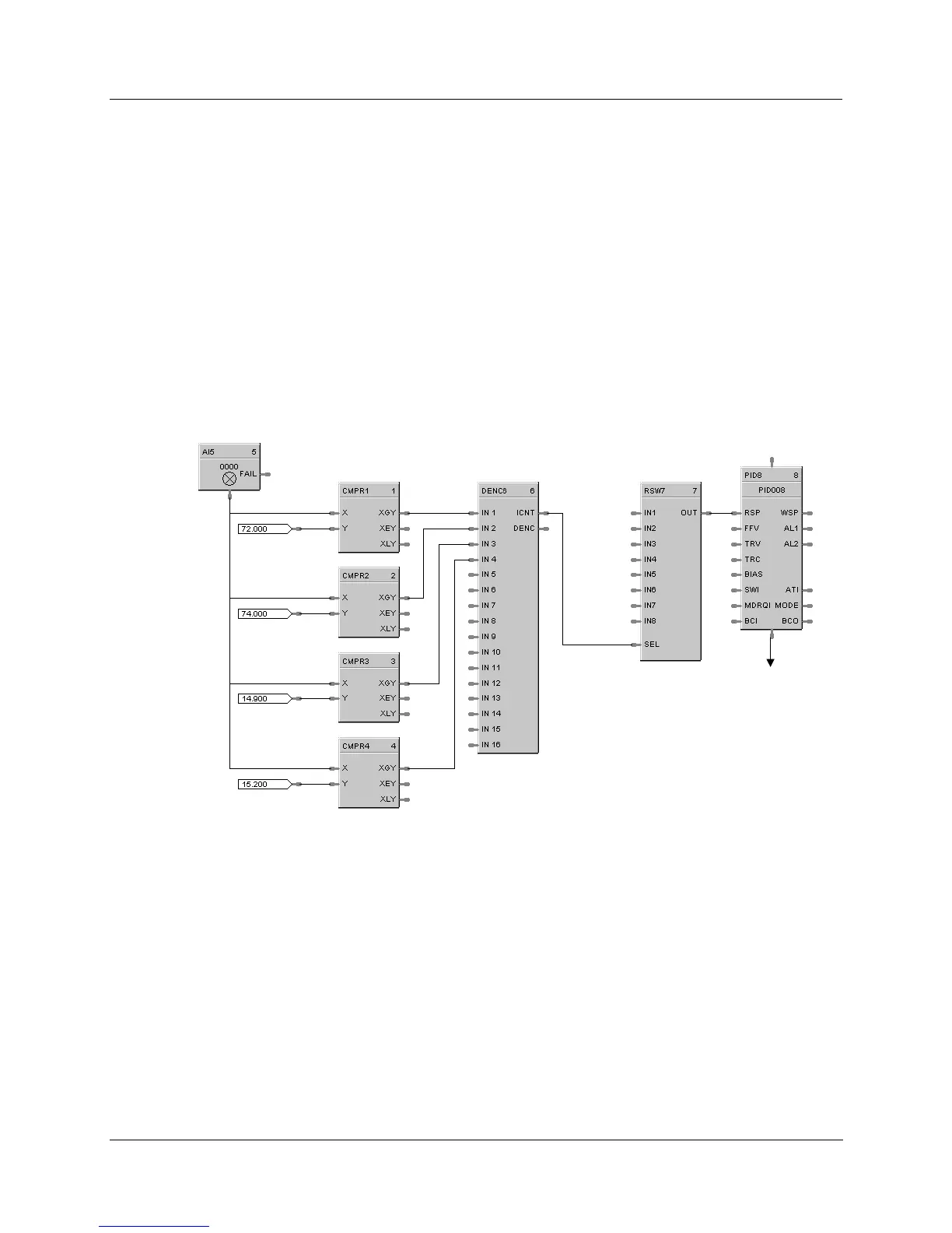
HFigure 28 shows a Function Block Diagram using a DENC function block using multiple digital status to
select an appropriate setpoint for a flow loop.
Temp 1
Temp 2
Pressure 1
Pressure 2
Setpoint 1
Setpoint 2
Setpoint 3
Setpoint 4
Setpoint 5
Setpoint 6
Flow
To Flow
Regulator
Figure 28 DENC function block example

Table of Contents

Other manuals for Honeywell HC900

Questions and Answers:

Question and Answer IconNeed help?

Do you have a question about the Honeywell HC900 and is the answer not in the manual?

Honeywell HC900 Specifications

General IconGeneral
SeriesHC900
RedundancyOptional
Programming LanguageFunction Block Diagram, Ladder Logic, Structured Text
InputsAnalog, Digital
OutputsAnalog, Digital, Relay
DisplayOptional
ControlPID, Advanced Control
Power Supply24V DC or 100-240V AC
Storage Temperature-40°C to 85°C
Humidity5% to 95% non-condensing
Communication ProtocolsModbus, Ethernet

Related product manuals