Function Blocks
PDE Peer Data Exchange Function Block
256 HC900 Hybrid Control Designer Function Block Reference Guide Revision 11
2/07
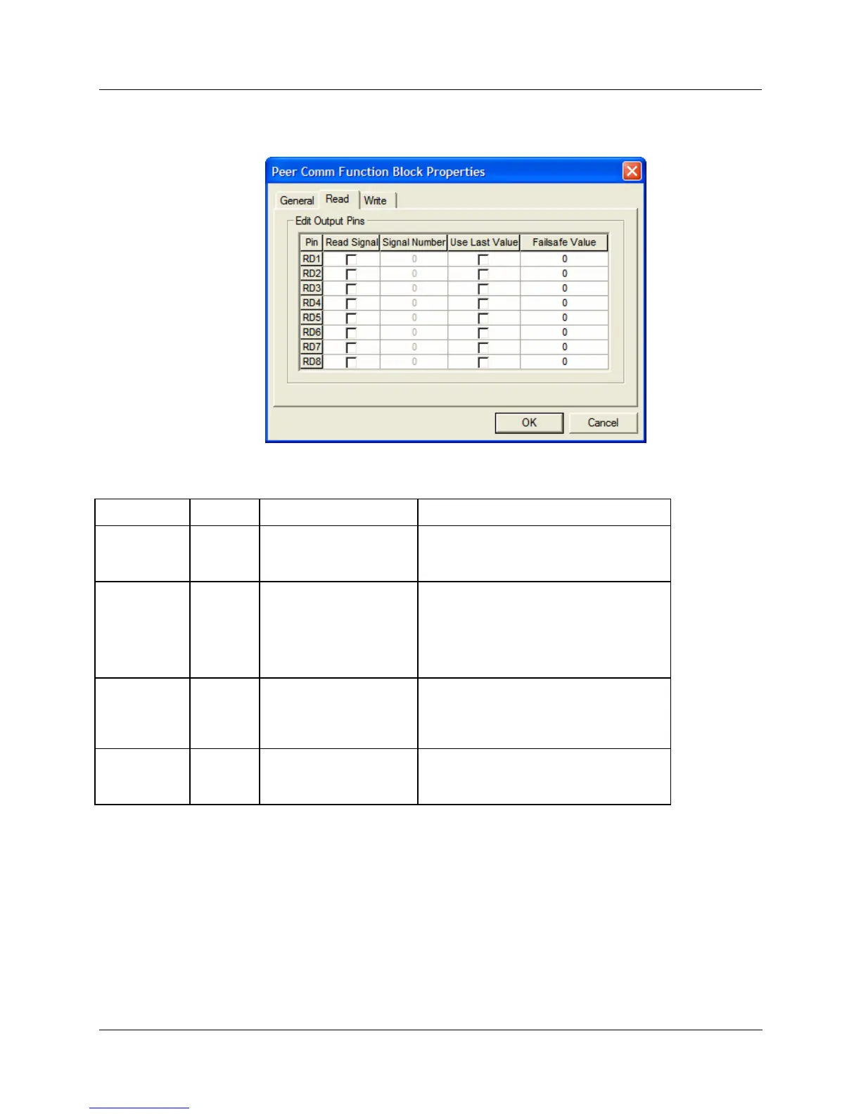
READ tab
Table 75 PDE Read tab configuration parameters
Parameter Index # Parameter Description Value or Selection
Read Signal
N/A
Activates the RD1
through RD8 pins for
reads.
Click on selection box for the pin number.
Signal
Number
N/A
Signal Tag number that
appears on the Tag
Information Report.
See "Tag Information
Example".
Enter a tag number from the report.
You can also use the "Find a Signal
tag" procedure to find the Signal Tag
number.
Use Last
Value
N/A
Use the last known
value for when the
associated data
connection is invalid.
Click on selection box for the pin number.
Failsafe
Value
41
through
48
Failsafe value for when
the associated data
connection is invalid.
Enter a failsafe value.

 Loading...


