Function Blocks
TCPS Function Block
Revision 11 HC900 Hybrid Control Designer Function Block Reference Guide 393
2/07
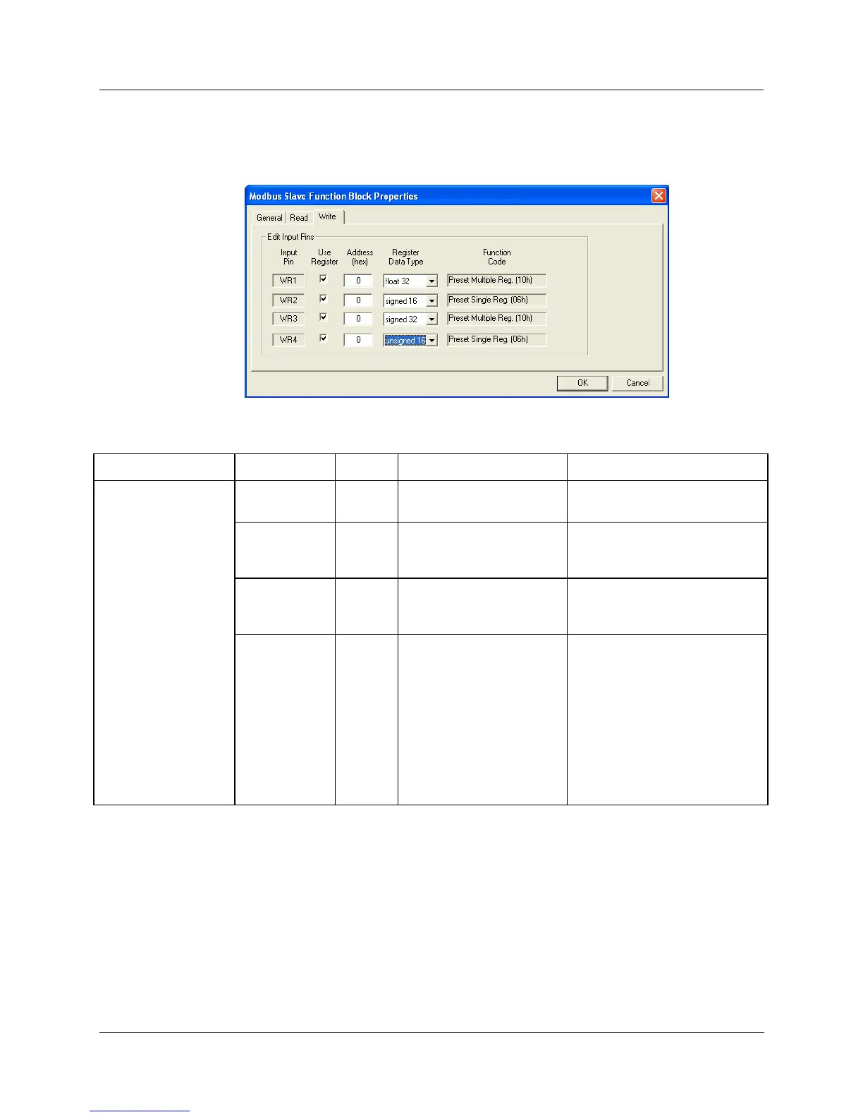
Write tab
It looks like this graphically. HTable 113 describes the parameters and the value or selection.
Table 113 TCPS Block Write tab configuration parameters
Properties Function Parameter Index # Parameter Description Value or Selection
Edit Input Pins Input Pin
N/A Input pin designation
Register request assigned to
WR1,WR2,WR3, or WR4 pin
Use Register
N/A Register Request
Click on the “Use Register” field
to assign a register to the Input
pin.
Address
(hex)
N/A Register Address
Type in the address of the Write
register (in Hex) on the slave
device
Register
Data Type
N/A Register data type
From the drop down menu,
select the Register Data Type
• Float
• Unsigned 32
• Signed 32
• Unsigned 16
• Signed 16

 Loading...


