Function Blocks
RAMP Function Block
310 HC900 Hybrid Control Designer Function Block Reference Guide Revision 11
2/07
RAMP Function Block
Description
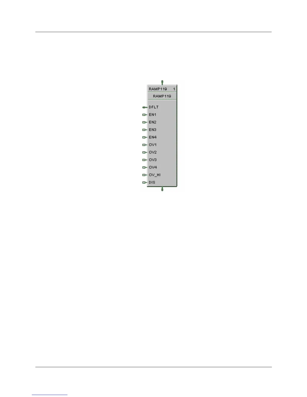
The RAMP label stands for Ramp.
This block is part of the
Auxiliary category.
Function
The RAMP function block is typically used for variable speed, valve position, and chemical feed control
applications to reduce the output value as more external devices are enabled.
For example: If one pump is running at 100 % and a second pump is enabled, the output value may be
rescaled to 50 % by the pump 2 enable signal.
The ramp block references an analog signal, and using four separate scales multiplexed together, provides a
single analog output over a programmed range.
A configurable signal lag [LAG TIME] is applied to the referenced analog input (PV). The highest enabled
scale [EN1-EN4] is applied to the lagged PV value. The output of the selected scale is then the output of
the function block [OUT].
A bumpless analog transfer over time is applied when switching between the selected scales. If no scales
are selected, then the default input value [DFLT] is written to the output.
If the block is disabled, the user configured [Off Value] is written to the output.
Turning ON an override input [OV1-OV4] sets its output (prior to multiplexing) high or low depending on
the state of the override input high [OV HI –
On or Off].
Each configuration is limited to 8 Ramp function blocks.
The general forcing of outputs is permitted within this block. Ramping and Clamping will not apply to the
output if it is forced.

 Loading...


