Function Blocks
AGA9UM Function Block
38 HC900 Hybrid Control Designer Function Block Reference Guide Revision 11
2/07
AGA9UM Function Block
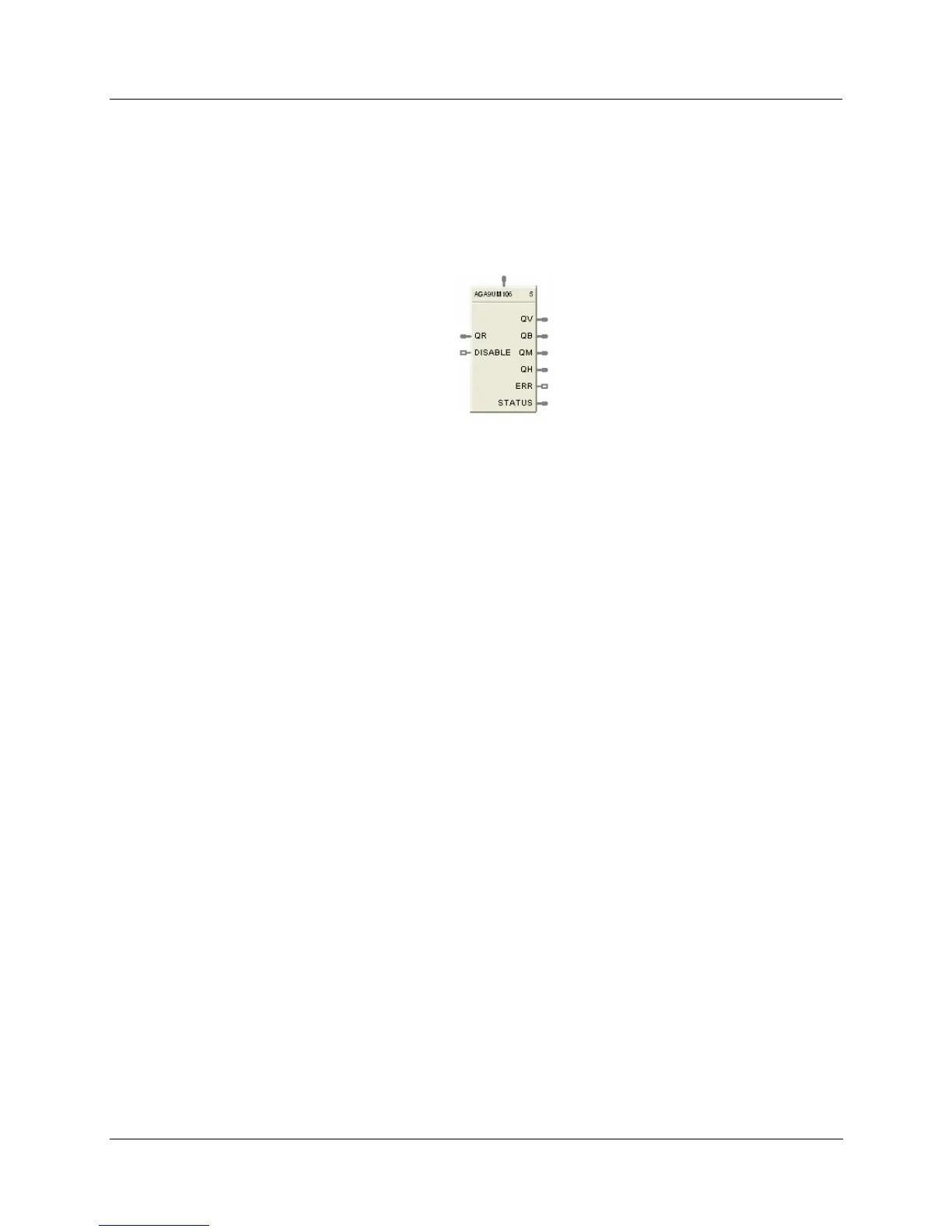
Description
The AGA9UM label stands for Ultrasonic AGA9 Meter Calculation.
AGA8 BLK
CONNECT
This block is part of the Calculations category.
Function
Calculations for gas flow measurements from multi-path Ultrasonic Meters - When connected to an
AGA8 block, the input value and multiple related parameters will be obtained from the AGA8 block. The
meter block will use this information to inherit the AGA8 block data for use in the calculations.
Inputs
QR = Raw Flow Rate in the units selected by the UNITS configuration parameter. U.S. is ft3/hr and
Metric is m3/hr.
AGA8 BLK CONNECT = When connected to an AGA8 block, the input value will equal the block
number of the AGA8 block. The meter block will use this information to inherit the AGA8 block data for
use in the calculations. If the input pin is not connected to an AGA8 block, then ERR and STATUS output
pins are updated accordingly.
DISABLE = When this pin is ON, the block is disabled, the process value outputs are set to 0, the ERR pin
is OFF, and the STATUS pin is set to 99 (See
HTable 5 AGA Error Codes).
Outputs
QV = Corrected volume flow rate at flowing conditions (Tf,Pf) in the units selected by the UNITS
configuration parameter. Output units are "ft3/hr" U.S. and “m3/hr” for metric.
QB = Corrected volume flow rate at Base (or Contract) pressure and temperature in the units selected by
the UNITS configuration parameter. Base or Contract conditions are specified by TB and PB in the
companion compressibility block. Output units are "ft3/hr" U.S. and “m3/hr” for metric.
QM = Mass flow rate in the units selected by the UNITS configuration parameter." Units are lbm/hr for
U.S. and kg/hr for metric.
QH = Energy flow rate in the units selected by the UNITS. Units are MBTU/hr for U.S. and
MJ/hr for metric.
ERR = Set when calculation status is indicating an error condition. Errors indicate a fatal condition. The
output values in this case will be set to 0 and the error pin turned on until configuration is corrected or
operating conditions return to normal.
STATUS = a status number is placed on this pin which can be used to find the error in the error/warning
lookup table (See
HTable 5 AGA Error Codes). This enables the user to connect the pin to comparator
blocks to distinguish various error/warning conditions in the function block configuration.

 Loading...


