Function Blocks
MBW Modbus Write Function Block
Revision 11 HC900 Hybrid Control Designer Function Block Reference Guide 205
2/07
Block properties
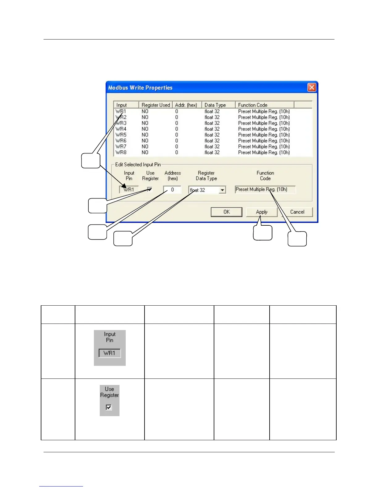
Double click on the function block to access the function block properties dialog box.
1
2
3
4
5
6
1
2
3
4
5
666
Configuration parameters
You must configure the MBW function Block Input Pins as shown in the “Edit Selected Input Pin” portion
of the dialog box. Follow the numbered sequence shown above referring to
HTable 63.
Table 63 MBW function block configuration parameters
Sequence
Number
Parameter
Field
Action Selections Comments
1
Click on an Input Pin
from the list of pins in
the upper portion of the
dialog box.
The selected Input Pin
will appear in the “Input
Pin” Field.
WR1 through WR8
2
Click on the “Use
Register” field to assign
a register to the Input
pin.
YES will be indicated in
the “Register Used”
column when you select
“Apply” .
WR1 through WR8

 Loading...


