Function Blocks
QDT Quadrature Function Block
300 HC900 Hybrid Control Designer Function Block Reference Guide Revision 11
2/07
QDT Quadrature Function Block
Description
The QDT stands for Quadrature.
This block is part of the
I/O Blocks category.
Function
This function block measures/controls movement of an actuated device. A digital encoder connected to the
actuated device produces two channels (A and B) of square waves, offset 90 degrees. Quadrature refers to
the 4 logic states between these two waves. The rising edge to rising edge (cycle) on channel A or B
indicates that one set of bars on the encoder have passed by its optical sensor. By counting these passing
rising edges the Quadrature block measures
1) distance (or whatever engineering units are being controlled by the device),
2) position (that is, distance from a marker designated as zero),
3) direction (indicated by the sequence between the two channels; A leads B or B leads A).
More precise measurement/control is done by counting more logic states determined by the two waves. For
example, the quadrature state of channels A and B create four unique logic states. When these four unique
logic states are decoded, the resolution obtained is 4 times (4X) the resolution of the encoder. So with this
in mind 250 cycles would yield 1000 quadrature states.
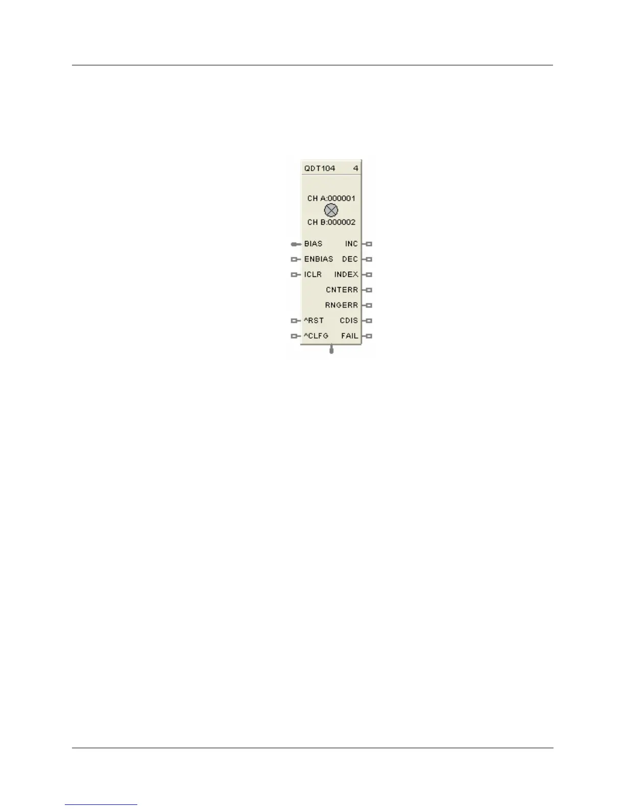
Inputs
BIAS
= Value added to the output in EU.
ENBIAS = Enable Bias. When ON the bias is added to the output. Input is ignored if not connected and
default state is enabled.
ICLR = Index Clear Enable. When this is ON it enables the module’s Index input so that the first OFF to
ON transition of Index input resets the output to zero (plus bias, if enabled).
^RST = OFF to ON transition resets the output to zero (plus bias, if enabled).
^CLFG = OFF to ON transition clears the CNTERR and RNGERR flags to zero.

 Loading...


