Function Blocks
TRIG Trigger Function Block
Revision 11 HC900 Hybrid Control Designer Function Block Reference Guide 425
2/07
Example
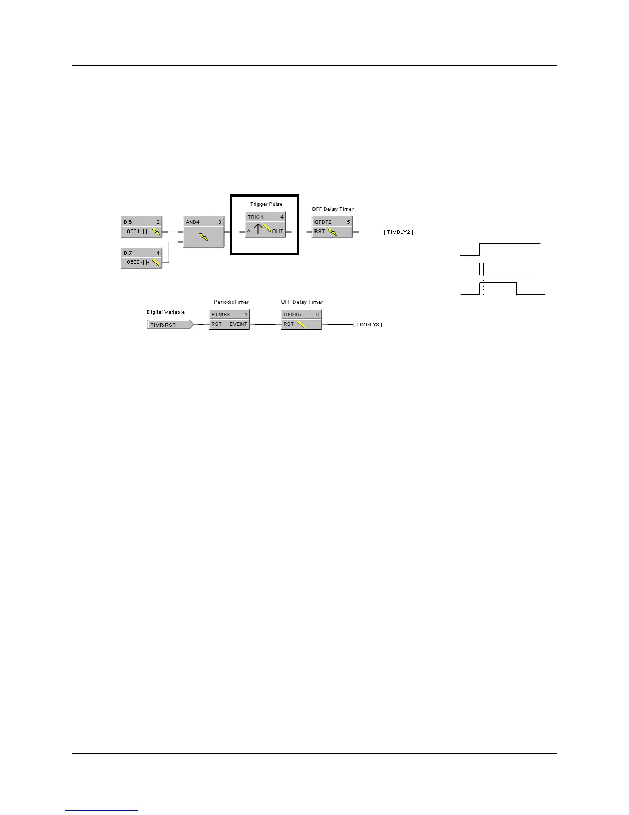
HFigure 117 shows a Function Block Diagram using a TRIG function block. An OFF delay timer block
output is ON as long as the RST input is logic HI (ON). It can be used for time duration but must be
triggered by an ON to OFF transition on the Reset input. This can be accomplished using
Trigger blocks
(TRIG)
to create one-shot pulses which last one scan cycle. The fast logic trigger pulse will last 100 ms.
while the normal logic trigger pulse will last the complete scan cycle for analog blocks. Use according to
application need. A Periodic timer output pulse may also be used to start the timer for the OFF delay.
Off delay
AND4 output
TRIG1 output
OFDT2 output
Timing Diagram
Figure 117 TRIG function block example

 Loading...


