Function Blocks
8DO Function Block
150 HC900 Hybrid Control Designer Function Block Reference Guide Revision 11
2/07
Block properties
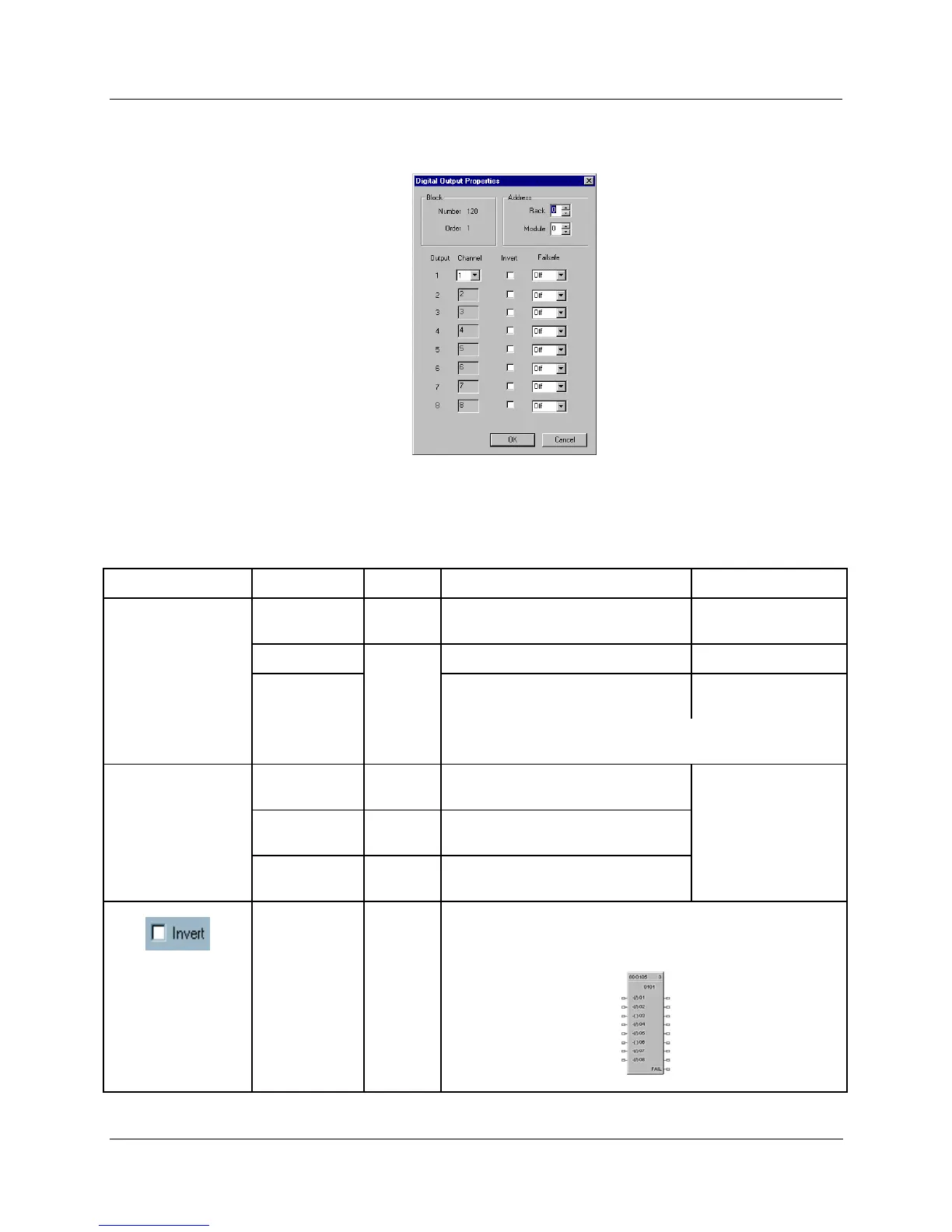
Double click on the function block to access the function block properties dialog box.
Configuration parameters
Table 46 Eight Digital output configuration parameters
Properties Group Parameter Index # Parameter Description Value or Selection
Output 1 through 8 Rack
N/A
Rack address of selected I/O
Module
From 1 to 5
I/O Module
Address of select I/O Module From 1 to 12
Channel
Channel on selected I/O Module
1 to 8, 9 to 16, 17 to
24, 25 to 32
NOTE: If you don’t want to use an output pin, leave the
Module # and Channel # at 0.
Failsafe Failsafe ON
N/A
set the output of the block to OFF
when failure is detected
Select from drop-
down menu
Failsafe OFF
N/A
set the output of the block to ON
when failure is detected
for each Output.
Failsafe
HOLD
N/A
hold the output at the last value just
prior to the failure being detected
1
If INVERT is selected, Invert IN before writing to output
The slash will be present in the COIL symbol only when the
invert box is selected on the dialog box. (See below.)

 Loading...


