Function Blocks
QDT Quadrature Function Block
Revision 11 HC900 Hybrid Control Designer Function Block Reference Guide 301
2/07
Outputs
INC
= ON when count is incrementing; OFF when count is stopped or decrementing.
DEC = ON when count is decrementing; OFF when count is stopped or incrementing.
INDEX = ON when index pulse is detected and ICLR are asserted.
CNTERR = ON when the count on the module overflows or underflows.
RNGERR = ON when the count on the module surpasses the range limits.
CDIS = ON when the PFQ module detects a cable disconnect.
FAIL = ON when module is failed. Caused by INC and DEC both ON.
OUT = Count in EUs.
Notes
To ensure correct counting, the block counts only pulses of a certain wavelength (>2.25 uS); smaller pulses
caused by noise are rejected. Additionally only a single transition of Channel A (Input 1) and Channel B
(Input 2) may occur; a transition on both channels simultaneously cases an invalid count.
Configuration Parameters
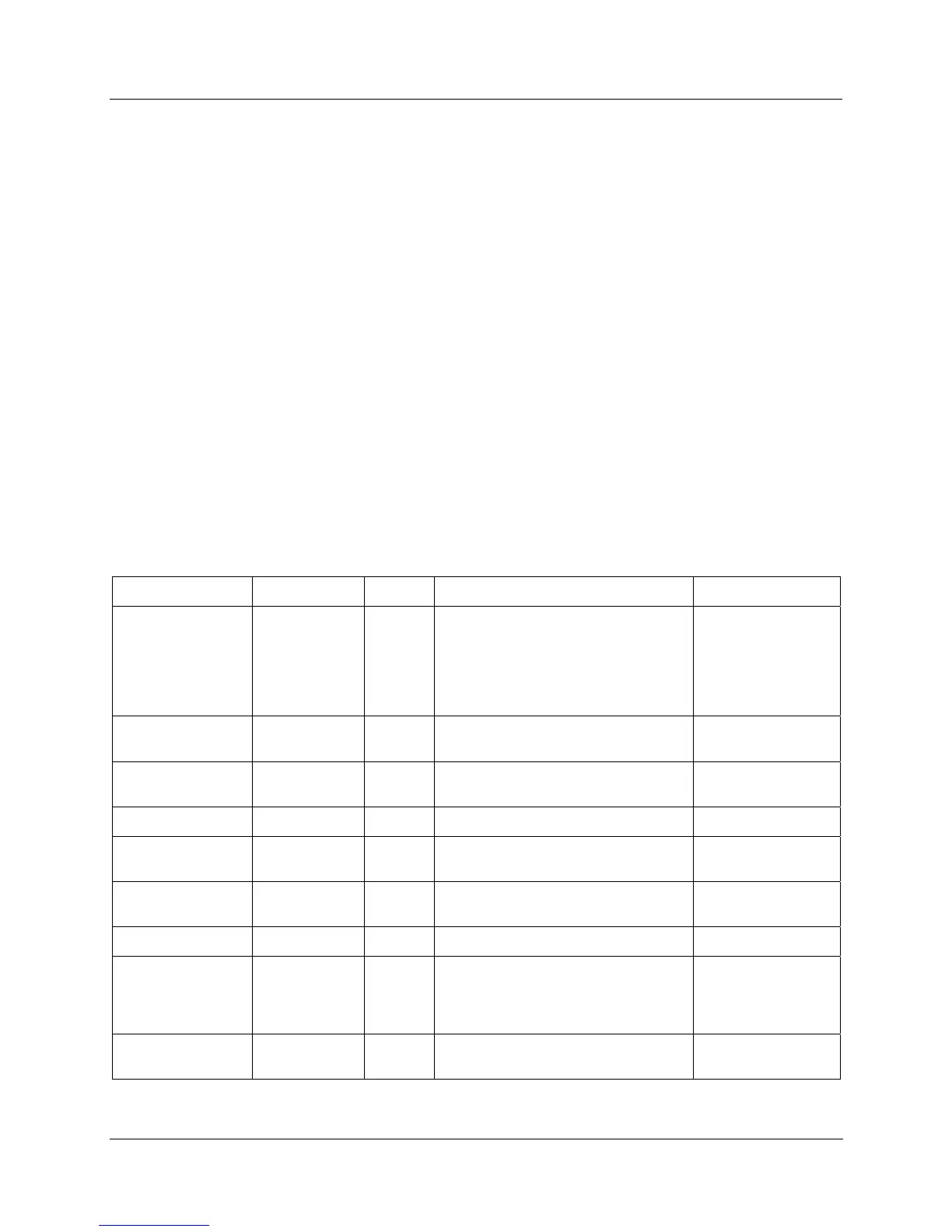
Table 88 QDT parameters
Properties Group Parameter Index # Parameter Description Value or Selection
Block Order
N/A Execution Order for Block
Read Only. To
change block order,
right-click on a
Function Block and
select Execution
Order.
Input A Address Rack
0
This is the address of the selected
Rack.
Enter a value:
from 1 to 5.
Module
0 Slot location of the PFQ module
Enter a value:
from 1 to 12
Channel
0 Channel A on the PFQ Module 1 (not selectable)
Input B Address Rack
0
This is the address of the selected
Rack.
Automatically set to
same as Input A.
Module
0 Slot location of the PFQ module
Automatically set to
same as Input A.
Channel
0 Channel B on the PFQ Module 2 (not selectable)
Encoder Range
Pulses per
EU
1
Number of pulses per EU of the
variable being measured/counted. Be
sure to factor in your Quadrature
Mode setting (X1, X2, X4).
Enter a value.
Upper Range
Limit
3 Upper range limit of EU. Enter a value.

 Loading...


