Function Blocks
FI Frequency Input
Revision 11 HC900 Hybrid Control Designer Function Block Reference Guide 161
2/07
Configurable Parameters
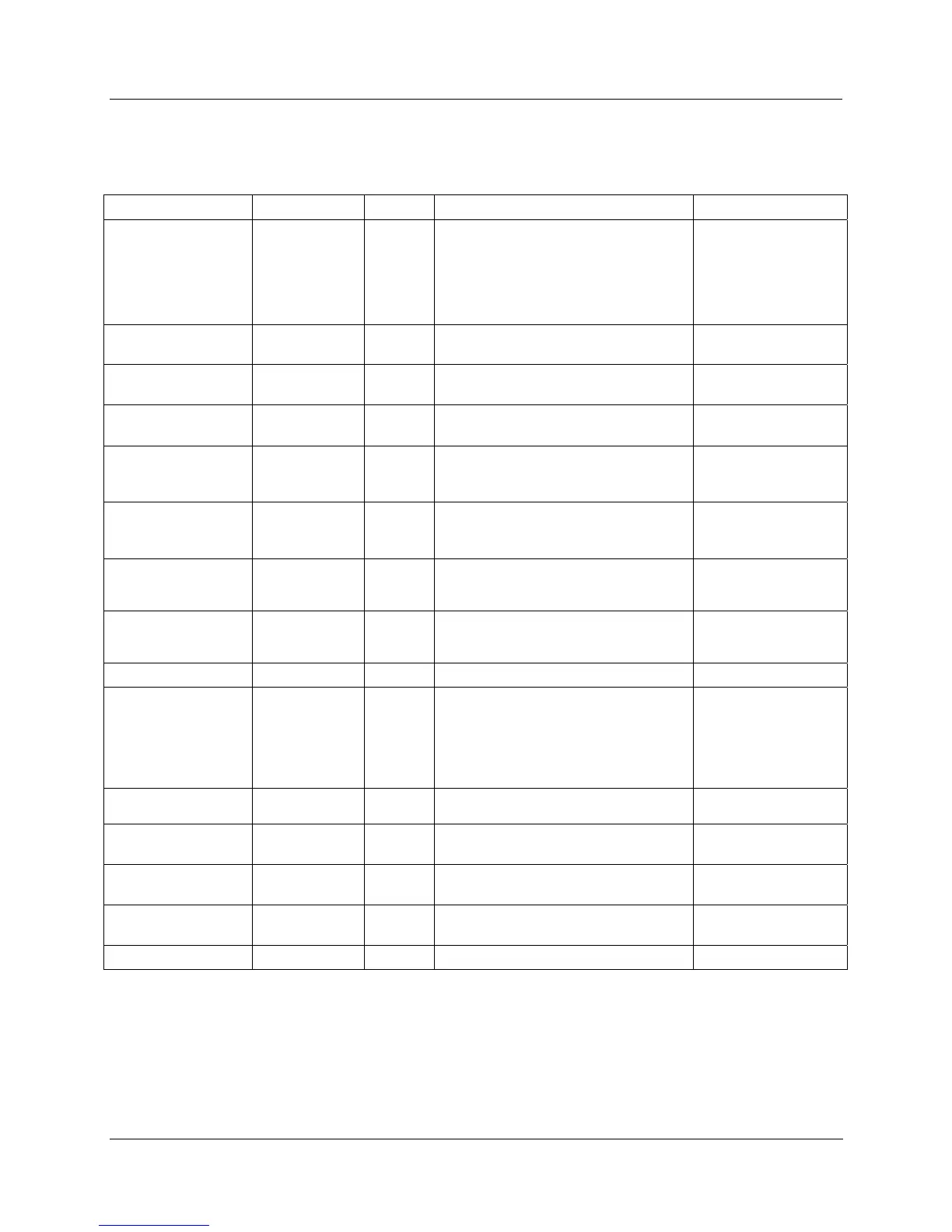
Table 48 Frequency Input configuration parameters
Properties Group Parameter Index # Parameter Description Value or Selection
Block Order
N/A Execution Order for Block
Read Only. To
change block order,
right-click on a
Function Block and
select Execution
Order.
Address Rack
0 This is the rack address of the PFQ
module.
Enter a value:
from 1 to 5.
Module
0 Module address of the PFQ module. Enter a value:
from 1 to 12.
Channel
0 Channel on selected Module. Enter a value:
from 1 to 4
Frequency Span Set High
Input (Hz)
7 High frequency value of the input
device. Exceeding this limit causes an
over-range error.
Enter value in Hz.
Set Low
Input (Hz)
8 Low frequency value of the input
device. Exceeding this limit causes an
under -range error.
Enter value in Hz.
Output Range in
EU
High (EU)
5
High range value. Frequency span in
Hz is scaled to the output range in
EU.
Enter value in EU.
Low (EU)
6
Low range value. Frequency span in
Hz is scaled to the output range in
EU.
Enter value in EU.
Settings
Bias
2 Bias value added to the output. Enter value in EU.
Pulse Width
(Range)
9
The input signal is rejected if it is
below this pulse width. The frequency
of pulses above this width must be in
this frequency range; otherwise the
output goes to failsafe and a failure-
to-convert error occurs.
500µsec (10Hz-
500Hz)
50µsec (10Hz-5KHz)
2.5µsec (10Hz-
100KHz)
Filter Time
(sec)
1 Filter time constant in seconds.
Enter value in
seconds.
Failsafe Use Value
3 When FAIL is ON output is set to this
value.
Click to select, enter
a value.
Up scale
4 When FAIL is ON output is set to
Upper Range Limit.
Click to select.
Down scale
4 When FAIL is ON output is set to
Lower Range Limit.
Click to select.
HOLD
4 When FAIL is ON output is held. Click to select.

 Loading...


