EasyManuals Logo

Honeywell HC900 Reference Guide

Honeywell HC900
456 pages
To Next Page IconTo Next Page
To Previous Page IconTo Previous Page
Page #152 background imageLoading...
Page #152 background image
Function Blocks
DI Function Block
138 HC900 Hybrid Control Designer Function Block Reference Guide Revision 11
2/07
Example
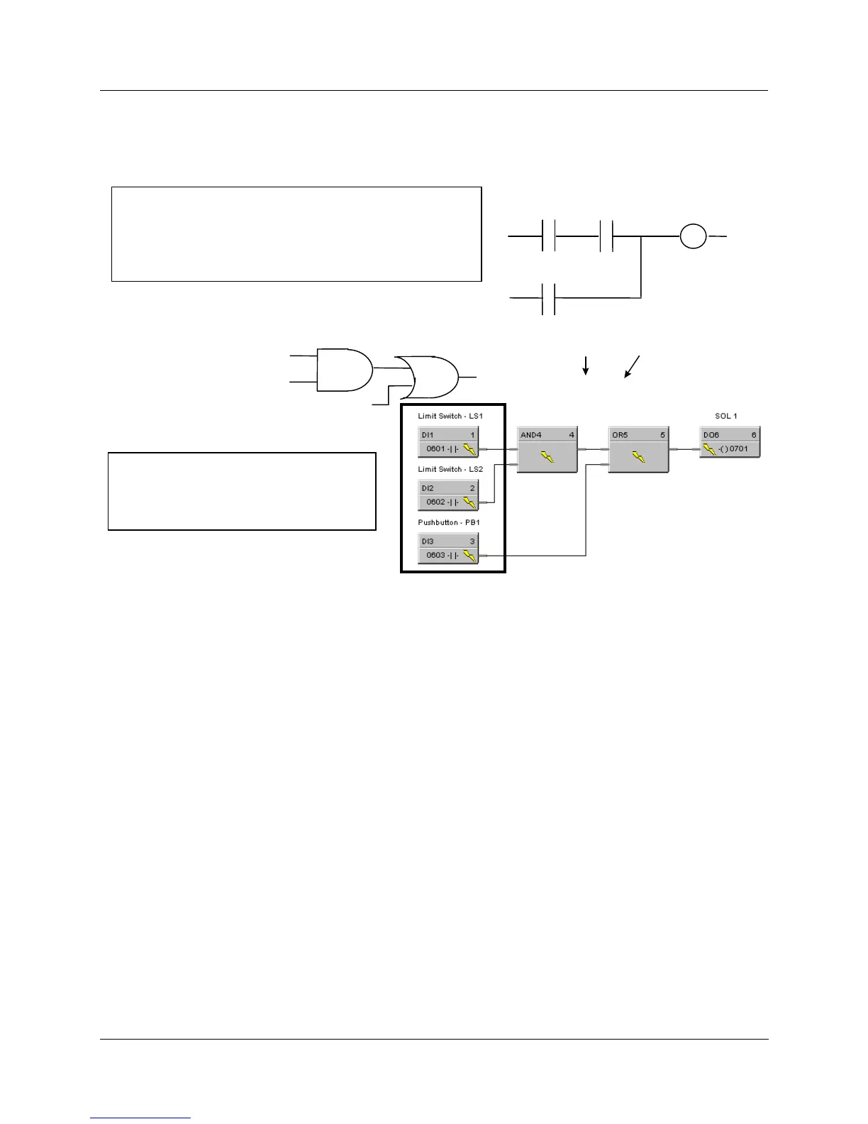
HFigure 30 shows a Function Block Diagram using DI function blocks in a basic Series Parallel Circuit.
LS 1
LS 2
SOL 1
Coil
This is a basic series-parallel circuit. If Limit Switch 1
(LS1) is ON and Limit Switch 2 (LS2) is ON, or
if pushbutton PB1 is ON, then Solenoid 1 is turned ON,
otherwise it is OFF. Note “power flow” can be delivered
in either of two paths to the solenoid.
PB1
Equivalent Boolean Logic Expression
HC900 Logic
A
= LS1,
B = LS2
D = Output
(A * B) + C = D
A
ND Symbol
A
B
C
C = PB1,
OR Symbol
D
OR
This uses a basic 2 Input AND block
and a 2 Input OR block.
6 Function blocks are used.
AND
Figure 30 Digital input function block example

Table of Contents

Other manuals for Honeywell HC900

Questions and Answers:

Question and Answer IconNeed help?

Do you have a question about the Honeywell HC900 and is the answer not in the manual?

Honeywell HC900 Specifications

General IconGeneral
SeriesHC900
RedundancyOptional
Programming LanguageFunction Block Diagram, Ladder Logic, Structured Text
InputsAnalog, Digital
OutputsAnalog, Digital, Relay
DisplayOptional
ControlPID, Advanced Control
Power Supply24V DC or 100-240V AC
Storage Temperature-40°C to 85°C
Humidity5% to 95% non-condensing
Communication ProtocolsModbus, Ethernet

Related product manuals