Function Blocks
MBS Modbus Slave Function Block
Revision 11 HC900 Hybrid Control Designer Function Block Reference Guide 199
2/07
Properties Function Parameter Index # Parameter Description Value or Selection
Modbus
Address
2 Address of Slave device
on the Modbus link
Enter unique address between
1 and 247
Default MB address = 255
which means slave will NOT be
in scan
Modbus Double
Register Format
Each IEEE 32-bit floating point number requires two consecutive registers
(four bytes) starting with the register defined as the starting register for the
information. The stuffing order of the bytes into the two registers differs
among Modbus hosts. The selections are:
Selection Description Byte order
FP B Floating Point Big Endian Format 4, 3, 2, 1
FP BB
Floating Point Big Endian with
byte-swapped
3, 4, 1, 2
FP L Floating Point Little Endian Format 1, 2, 3, 4
FP LB
Floating Point Little Endian with
byte-swapped
2, 1, 4, 3
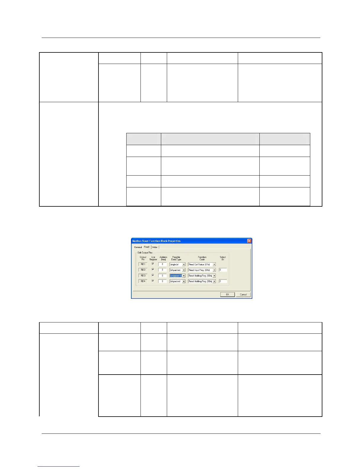
READ tab
It looks like this graphically. HTable 61 describes the parameters and the value or selection.
Table 61 MBS Block Read tab configuration parameters
Properties Function Parameter Index # Parameter Description Value or Selection
Edit Output Pins Output Pin
1 Output pin designation
Register request assigned to
RD1, RD2, RD3, or RD4 pin
Use Register
2 Register Request
Click on the “Use Register” field
to assign a register to the
Output pin.
Address
(hex)
N/A Register Address
Type in the address of the
Read register (in Hex) on the
slave device
NOTE: A single configuration
may contain up to 256
enabled registers.

 Loading...


