Function Blocks
TOT Totalizer Function Block
Revision 11 HC900 Hybrid Control Designer Function Block Reference Guide 405
2/07
Example
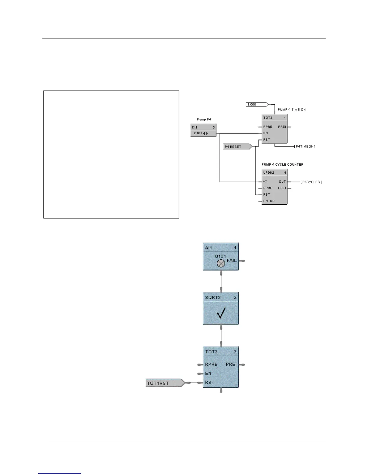
HFigure 114 shows Function Block Diagrams using a TOT function block.
EXAMPLE 1
In UMC ON Delay timers are not retentive - if the RUN
input is logic 0, the timer is reset. A retentive timer has
an Enable and a Reset input. As long as the timer is
not reset, time will be accumulated when the Enable
Input is logic 1 (ON). This permits recording the time a
device such as a pump has been on.
This example uses a Totalizer function block as a
retentive timer. If a fixed input of 1 is provided to the
block using a Numeric Constant, the totalizer will time
up to 1 at the input rate selected (per sec, per min., per
hr, or per day). For example, if the “per hr” rate were
selected, the output would be 1.0 after 1 hour, 2.0 after
2 hours, etc, up to the Preset value.
A counter is shown to count the number of pump cycles
(On to OFF transitions).
The P4-RESET Digital Variable is used to reset the
timer and counter
EXAMPLE 2 - FLOW TOTALIZATION
Figure 114 TOT function block examples

 Loading...


