Function Blocks
FGEN Function Generator Function Block
158 HC900 Hybrid Control Designer Function Block Reference Guide Revision 11
2/07
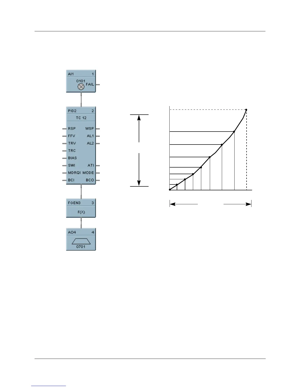
Examples
HFigure 37 shows a function block diagram using a FGEN function block to characterize the PID control
loop output for control valve operation using 9 breakpoints.
OUT9
OUT8
OUT7
OUT6
OUT5
OUT4
OUT3
OUT2
OUT1
X1 X2 X3 X4 X5 X6 X7 X8
Compensating for control valve characteristic
100%
0%
0% 100%
FGEN
OUTPUT
PID OUTPUT
Figure 37 FGEN function block example

 Loading...


